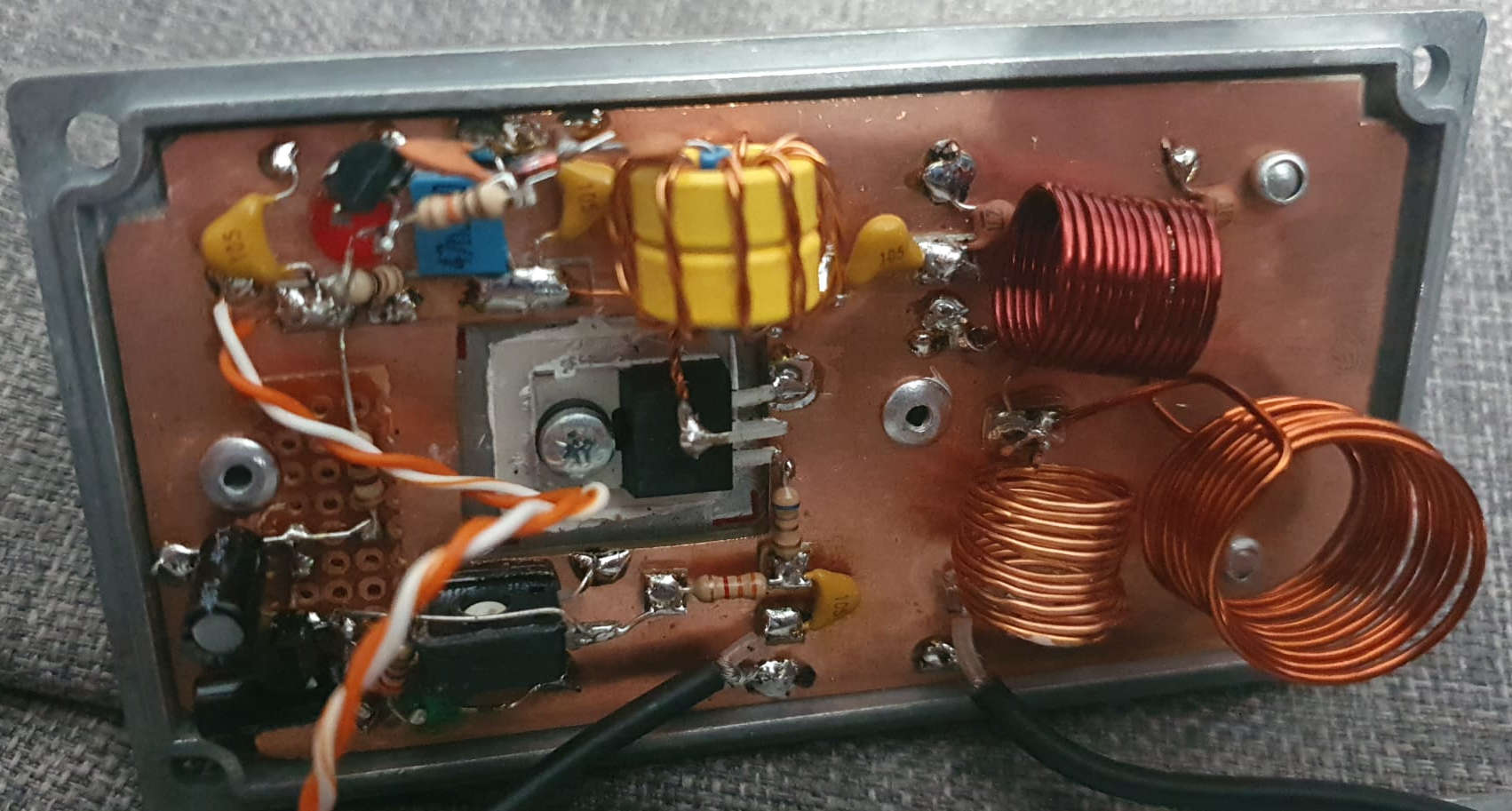
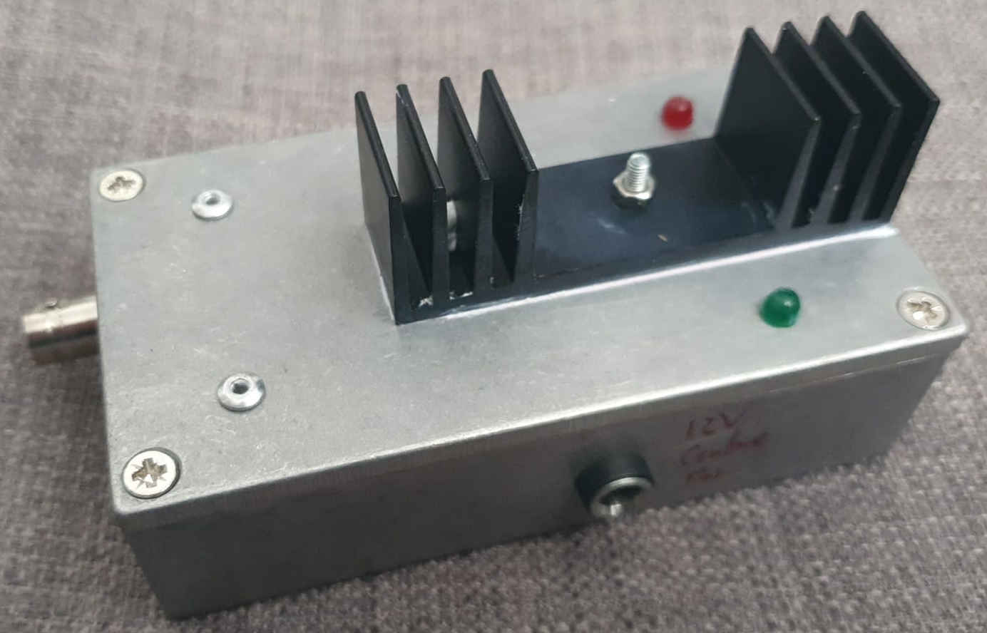
I seem to have lost some of my notes for this one, but essentially it's a QRP 5W 40m PA based around the IRF510 MOSFET. It was probably inspired by these designs: https://www.qsl.net/kd7rem/5wpa.htm and https://qrp-labs.com/qcx/qro.html - especially the latter but not driven nearly so hard. I'll keep digging because I am certain I made some measurements of its performance, and have a full schematic somewhere. That said it's very conventional, single ended mosfet bised for a few tens of mA DC, 1:2 transformer output, 3-inductor low pass filter. The bias supply is regulated and then just set with a potentiometer. The only slightly uncommon thing is the carrier-detect LED, which is lit by a very simple RF detector fed from its own single-turn winding on the output transformer.

- Contruction notes:
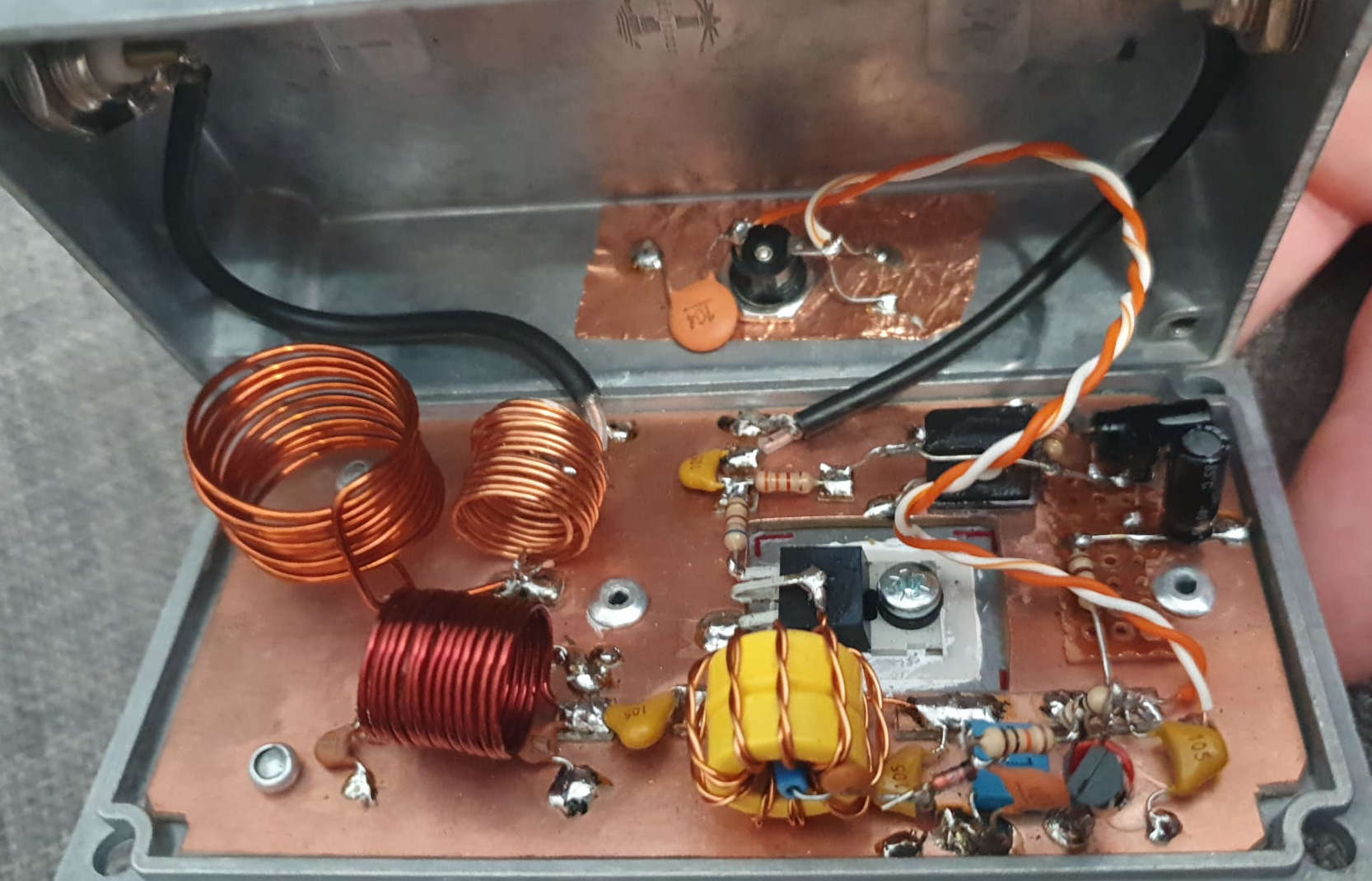
- I prefer building things like this into the lid of the box rather than the base as it keeps it all more acessible.
- The copperclad board forms a continuous ground plane and is pop riveted to the box lid.
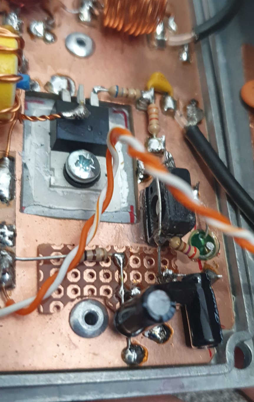
- Mosfet screwed rather than riveted so that it can be replaced if needed, and also because I have read that pop riveting can cause bond wire failure from the shock.
- Smallber bits of copperclad are glued on as needed to provide the other circuit nodes.
- Component leads and connection lengths more generally kept as short as possible for the components in the RF path.
- Inductors in the filter all placed orthogonal to each other to minimise coupling between them.
- Power input connector has local decoupling to the box to minimise RF leakage.