The dynastarter on the dumper truck needed a regulator, and I wasn't convinced the traditional mechanical regulator would be reliable on a high-vibration machine used in a damp environment. Clearly an electronic regulator is the answer. I have based mine on a design by Manfred Mornhinweg with a few changes:
- The schottky diode and current shunts are seperate external devices, so the charging current does not enter the electronics enclosure at all
- The current shunt is a commercial 30 A, 75 mV unit, with resistor values in the regulator adjusted accordingly.
- R2 was changed to 56 Ohms to set a 22 A current limit with the 75 mV / 30A shunt
- Various minor component swaps to match the contents of my junkbox.
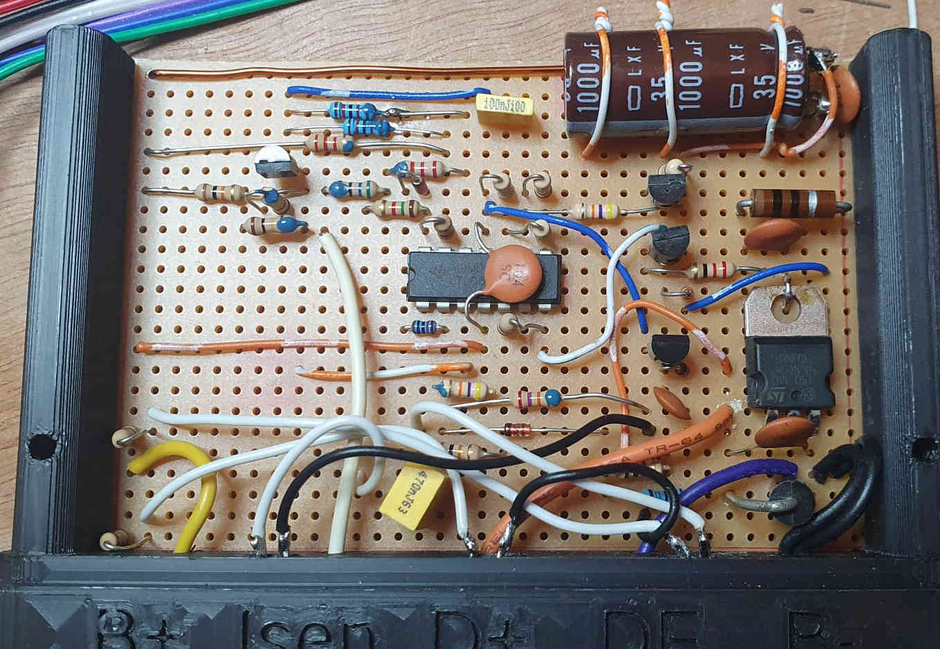
- 1% resistors weren't used, instead the critical resistors were hand-selected from 5% parts using an accurate bench DMM. Those are the resistors with a dot of turquoise paint in the photos
- I used a TL431A as U2, with two 100k feedback resistors (selected to match) to make it 5 V. I could have connected reference directly to kathode and rescaled all the other resistors in the circuit, but this approach minimised the change.
- Q1-Q4 and D8 were all changed to suit what I had available
- C8 was reduced to 1000 μF to save space.
A simple test circuit was created allowing me to approximate the dynamo on the bench. A 1 Ohm resistor and 1N4001 diode replaced the external shunt resistor and diode, and a bench supply simulated the battery and dynamo. To allow the supplies to sink as well as source current the bench supply outputs were loaded with 100 Ω resistors. The field output was connected to D+ via a blue LED, resistor, and large inductor (the primary of a small transformer) which converted the PWM back to a variable current.
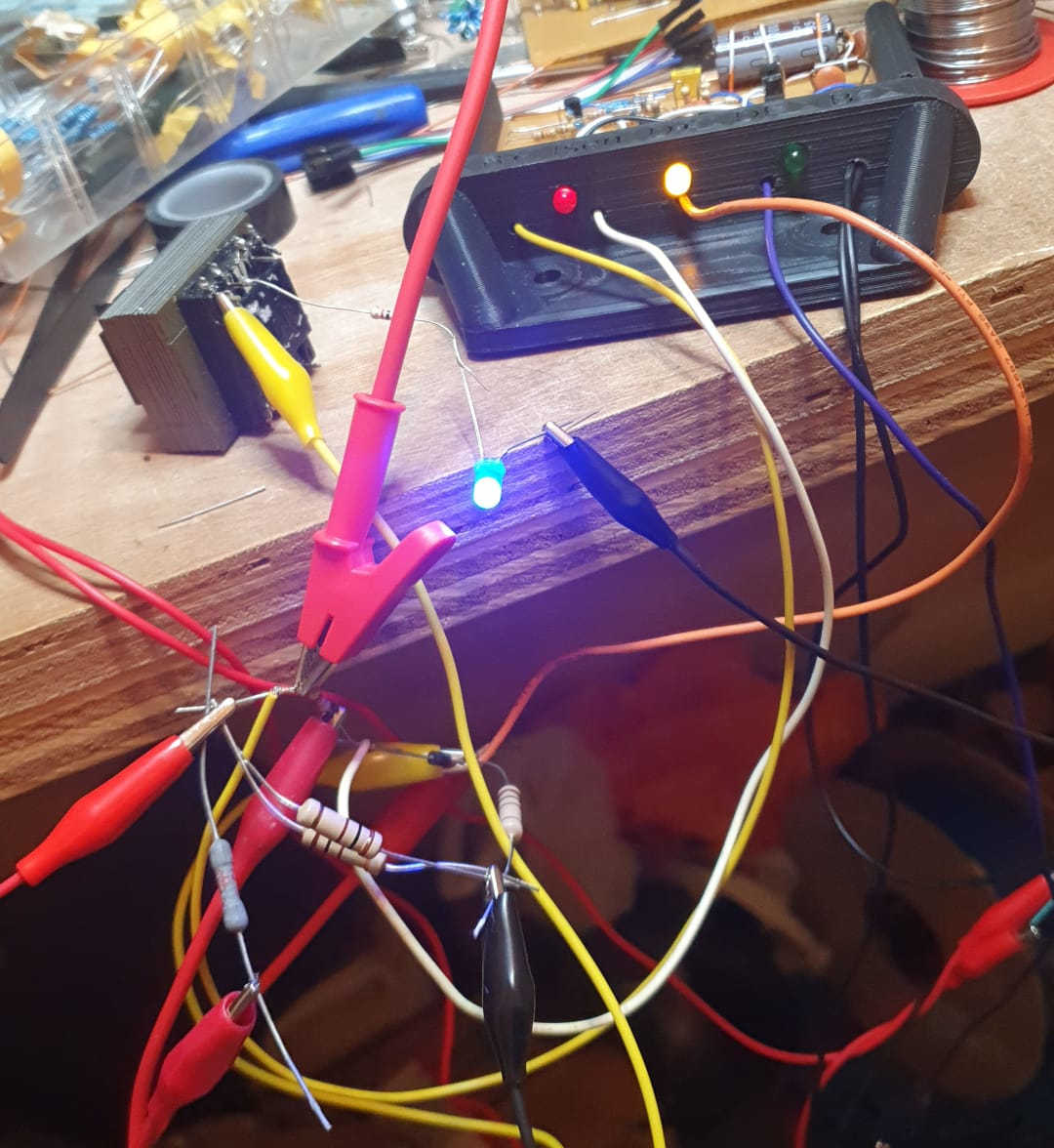
With this setup I was able to run through the essential functions of the controller, albeit open-loop. Everything seemd good, other than that with the high gain of the current regulating amplifier I wasn't able to observe linear operation, instead it just suddenly switched on and off when the threshold is crossed no matter how finely I tried to adjust things. That is fairly expected when running without feedback.
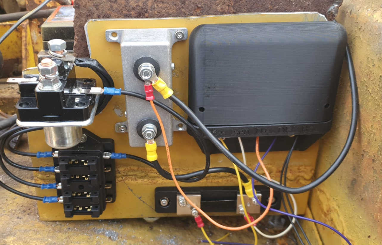
So, the next thing is to install it on the dumper. So, here it is, together with the current shunt (bottom right) and high current schottky diodes (diecast box centre). Dynamo output comes in on the thick black cable from the right, to the diode with the orange wire tapping thiss off for the regulator, then to the right hand side of the shunt where the white wire takes the voltage there to R2. The left of the shunt connects via the fusebox to the battery (some wiring not shown) with the battery positivie being fed to the regulator on the yellow wire. The big thing at the top is the starter solenoid, it's just a convinient place to pick up the battery positive terminal.
So on to testing. It mostly works. Initially the regulator is off and the current draw correctly low. On starting the engine the yellow LED comes on, with around 5 V measured on the dynamo output. So far so good. On increasing engine RPM the voltage increases to around 13 V, but then oscillates around that point. The green LED can be seen to be flashing dimly at a few Hertz. Clearly the control loop is unstable! Most likely my dynastart differs significantly from Manfred's, and that's upsetting the regulator. With such a low frequency misbehaviour it seems unlikely to be a wiring inductance problem unless there is some other higher frequency oscillation that's actually the root cause and the low frequency behaviour I am seeing is due to bias shifts from that (“squegging”). The current control loop is not involved as the current never rose high enough due to a fully charged battery, evidenced by the red LED remaining off. My next task is to try and understand what's happening here and make some tweak to the controller (currently a simple integrator) to give stable operation.
I can get similar oscillations in SPICE if I model the output inductance of the dynamo armature. Adding in other impedances to represent the wiring, etc. seems to have minimal effect. These simulated oscillations can be somewhat supressed (decaying oscillations indicitive of low phase margin) by placing a 33k resistor in series with C4, but this is probably not really sufficient.
Let's think about the control loop for a moment, and arbitarily start at the output of the error amplifier, U1 pin 1. This control voltage is converted to PWM by U1B, when the dynamo is output around 14V the gain of this is approximately 2, and there is a delay of around half a cycle, so 5 ms. This PWM voltage is integrated by the dynamo field winding inductance, to produce a current that has a 90 degree lag. Well, above the frequency given by f = R / (2 * π * L) anyway. That field current then results in a voltage out of the armature. The gain here is set by dynamo turns ratios and engine RPM, but it seems reasonable to think that at typical RPM we might need 50% duty cycle to get the right output, so the voltage gain is probably not that far off 2. This voltage then passes through a resistor divider with a gain around 1/3, and an inverting integrator with a high DC gain amd an additional 180+90 degree lag. Hmmm, depending on the R/L ratio of the field winding perhaps we would not expect it to be stable.
Heading back to SPICE, I created a simplified model where the PWM modulator and mosfet was replaced with a 5 ms delay and a voltage controlled voltage source. Not quite right as it doesn't capture the change in effective gain with dynamo voltage (a kind of squaring action) but it needs to be linear for an AC analysis. I then broke the loop and simulated the result, which showed the expected 180 degrees at DC, reaching zero degrees at around 2 Hz, at which point the simulated gain is around -7 dB, based on this it should be stable, but only with a 7 dB gain margin. 0 dB gain occurs at 1.4 Hz, with a phase margin of 8 degrees. It's easy to see why it's unhappy and given the margin of error in the model (especially uncertainty about dynamo characteristics) why it oscillates in the real world. The SPICE model is almost certainly not very accurate, but I find it makes it easier for me to visualise what's happening, even if the absolute numbers may be way off.
Things we could try to improve the phase margin include:
- A resistor in series with C4.
- This makes the intergrator behave like a simple inverting amplifer at higher frequencies, winning 90 degrees over that range
- In simulation a 47k resistor improves the gain margin at 1.5 Hz where the gain crosses zero from 5 degrees to 17 degrees. It has neghligible effect on the gain below this frequency, but gain at 10 Hz is about 10 dB higher.
- 100k brings the phase margin to more like 30 degrees.
- A capacitor or resistor-capacitor combination across R11
- A 1 μF capacitor also brings the phase margin at this frequency up to 30 degrees.
- 4.7 μF pushes the gain up as well, bringing the 0dB point to 3.2 Hz where the phase margin is now 75 degrees.
- Adding a series resistor, say 5.6k, keeps some of the phase benefits (50 degrees phase margin) whilst reducing the effect on high frequency gain.
- Reducing the delay in the PWM modulator by increasing its frequency
- Probably not that helpful on its own as the 5 ms or so from the current oscillator frequnecy is not dominant at the frequencies where there are problems.
- Combining 1 (with 100k) and 2 (4.7 μF and 5k6) gives a 4.7 Hz 0dB point, at which time the phase margin is 93 degrees. The gain at 2 Hz is increased from -5 to +5 dB which is fine, but the gain at 100 Hz (the modulator frequency) is also increased from -83 to -34 dB which is less good. Shunting the new 100k with 100nF reduces the phase margin by 10 degrees but the gain above 50 Hz by 10 dB, it might be worth doing.
With these additional tweaks operation in voltage limit mode is pretty well behaved in simulation. In current limit mode it still looks like it switches the field winding multiple times per clock cycle. This happens because the high-gain current control loop pulls the control voltage around rapidly and asymetrically, overshooting and then being pulled back by the voltage control. To some extent it may be characteristic of the circuit design, but what happens if we reduce the bandwidth of the current control amplifier? 100 nF in parallel with R8 seems to help it settle to a stable state, though with some initial decaying oscillations after a heavy load is applied. A 4.7 μF capacitor across R5 seems to help with those substantially though brings back some level of multiple pulses per cycle. Once again increasing the main oscillator frequency seems to help with that, this time to only 200 Hz seems enough.
SPICE-ing the current limit properly, it looks like the gain reaches unity at 31 Hz, with -37 degrees phase margin (with the voltage opamp changes only). The 100 nF capacitor moves this down to 9 Hz, but -55 degrees, the 4u7 brings some phase lift but not enough to look stable. The other place to add some differntiation is a capacitor across R10, which seems to have a little benefit in simulation. I am inclined not to worry too much about the current regulation until I have seen what it does in the real world, especially after the voltage amplifier changes (which affects both).
None of these simulations are likely to be especially accurate, but they give me some guidance as to what to try on the actual device, where removing, soldering, running the engine, etc. make test cycles a bit time consuming. And loud, given the new exhaust hasn't been fitted yet.