This is based loosely on the design from http://www.alternatezone.com/electronics/freq.htm but with some significant modifications. I have retained the 4553 based counter which I think is quite neat (though the 4553 seems rather hard to get hold of) but changed the clock source and the prescaler. An ex-equipment 10 MHz OCXO now provides the master, divided down to a 1 second gate time. A PIC is now used to generate the gate time precisely and also allows for an update time only slightly slower than the gate time rather than exactly half as in the original design. The new prescaler should be much faster and separate input amplifiers have been added, selected based on the kHz/MHz switch which also enables or disables the prescaler.
All images on this page are low resolution versions. Click them for bigger versions.
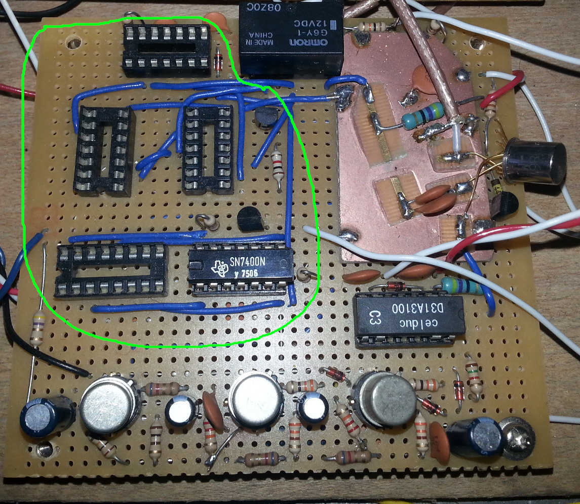
Counter
As mentioned previously this is based around the MC14553B 3-digit binary counter. These are run at approx 6V in this design, at 5V they have a minimum guaranteed clock speed of 0.9 MHz, typical value 1.5 MHz. 1 MHz is needed in this design so with the extra volt these should be fine. As in David Jones' design the counters are slaved together so that their output multiplexing is synchronous, and the 4511 decoders are also multiplexed. The slightly odd supply voltage of 6V allows the counters to interface between the decoders which must necessarily run at the LED voltage and the logic at a more conventional 5V. With a different decoder that could drive common-anode displays this little trick would not be needed.

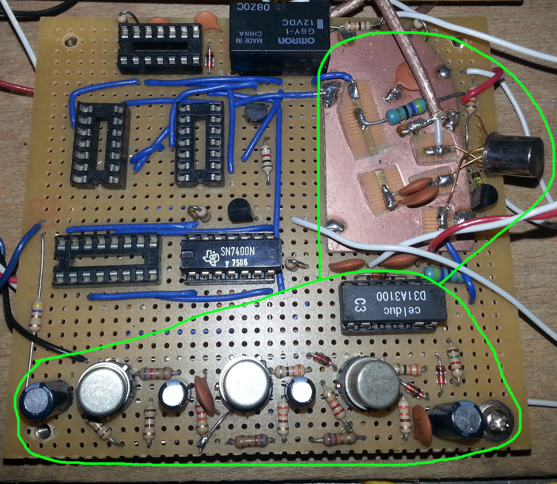
Prescaler
The first and fastest stage of the prescaler uses a 5 stage Johnson counter to divide the input frequency by 10. Two divide by 10 counters then follow for an overall divide by 1000. The 10 MHz reference oscillator may optionally be inserted before the last divide by 10, this provides a self-test function whereby exactly 1 MHz is fed to the counters and the display should read 000.000
Input Amplifiers
There are two input amplifiers, these are selected at the same time as the prescaler, i.e. the high frequency input stage is permanently connected to the prescaler and the counter is switched between the prescaler and the low frequency input stage. Simultaneously a relay directs the front panel connector to one or other of the amplifiers.
The low frequency amplifier uses a chain of BFY51s. It has a selectable input impedance between 50 Ohms and “high” which is around a kilohm. The last stage should clip and provide a suitable logic level drive to the counter.
The high frequency amplifier is based on a MMIC amplifier chip. It is placed on a small area of copperclad board attached to the prescaler board. No high-impedance input option is provided.
Reference and Counter Gating
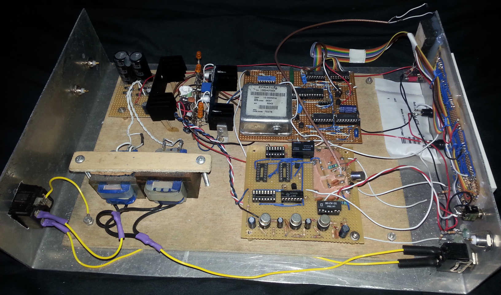
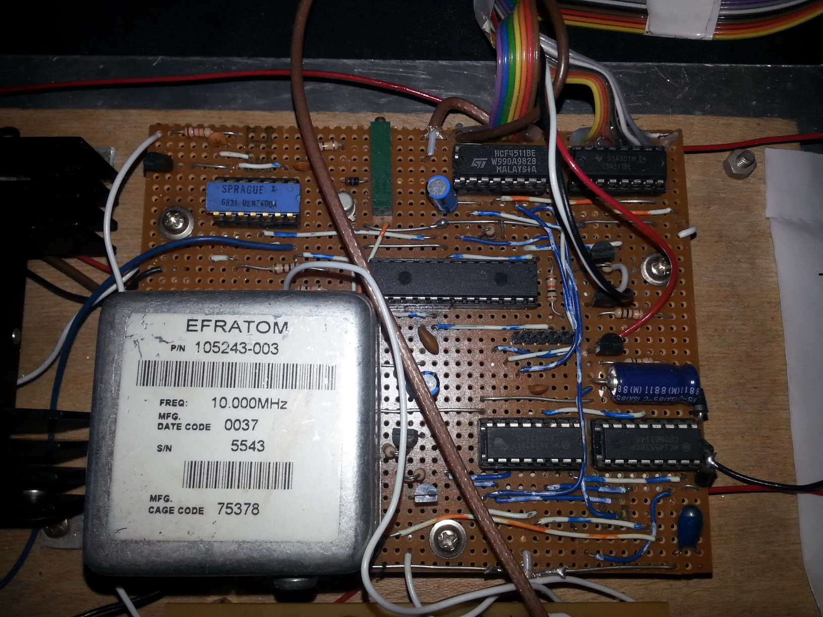
The internal reference is an Efratom 105243-003 OCXO which provides a 10 MHz master clock for the system. An input is provided for an external 10 MHz reference, an appropriate signal on that input will result in automatic switch-over to the external clock. A clock-out is also provided. The reference selector uses a diode detector on the RF input to drive an arrangement of NAND gates which switch over the reference clock.
The PIC is clocked directly from the 10 MHz reference. It enabled the external counters for exactly 2.5 million instruction cycles before disabling it then toggling the strobe and reset lines. The counters thus count for ten million cycles of the reference oscillator, the count is stopped, the count latched into the output buffer, and the counters reset. The process then repeats, taking fractionally more than one second and defining the update rate of the display.
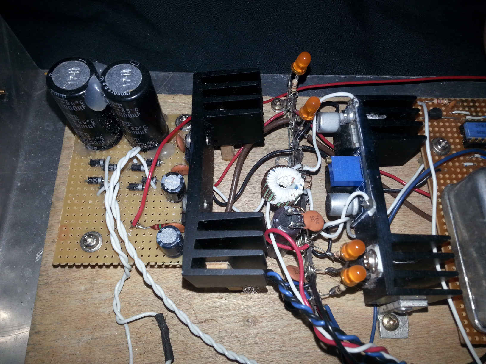
Power Supply
The OCXO needs 24V for its heater and a separate supply which may be lower for the oscillator, I used 15V for the oscillator as that was in the ebay listing and it seems happy but I don't have a full datasheet and I see other people have used 24V for both. The logic runs at 5V, the LEDs at 8V as their forward voltage is a little high.
To provide this assortment two 15V transformers are used. One is rated at 400mA and one at 600mA as they are what I had lying around. They are individually rectified and connected in series with the higher current one the lower of the two. The high voltage tap supplies the 24V linear regulator which in turn supplies the 15V one. These two regulators are mounted on the left hand heatsink in the photo. The low voltage tap supplies a cheap LM2596 module providing the 8V for the LEDs and this in turn supplies a 5V linear regulator for the logic. These are mounted on the right hand heatsink with some filtering on the tag strip. The 6V supply for the counters is derived from the 8V with some series diodes.
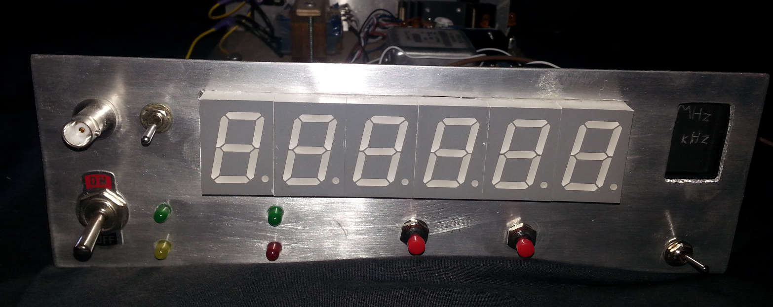
Front Panel
The six 7-segment displays are mounted on perfboard and connected via ribbon cable. The middle decimal point is permanently illuminated and an edge-lit display shows kHz/MHz depending on if the prescaler is switched in. Additional LEDs indicate the status of the reference, etc.