This started as a quickly thrown together project to get something running, so it was built around junkbox components. It then expanded in scope a little to the point where I should really have done things a little different from the begginging. Still, that just means there's scope for a V2 (which should probably be CDI).
So, the basic idea. You've got an engine which won't start due to a weak magneto. Perhaps someone left it out all winter under a tarp? You'd like a quick and easy way to get it going so you can debug other problems. That, or perhaps the ignition kinda works, but you have some mystery fault and you're not sure if it's ignition related or not. Anyway, this box of electronics connects to the weak magneto output, uses that as a trigger, then generates it's own much more powerful spark. It also provides an output for an LED strobe to check timing, and an option to trigger it with a Hall sensor input instead so you can just stick a magnet to the flywheel.
So, here's the schematic:
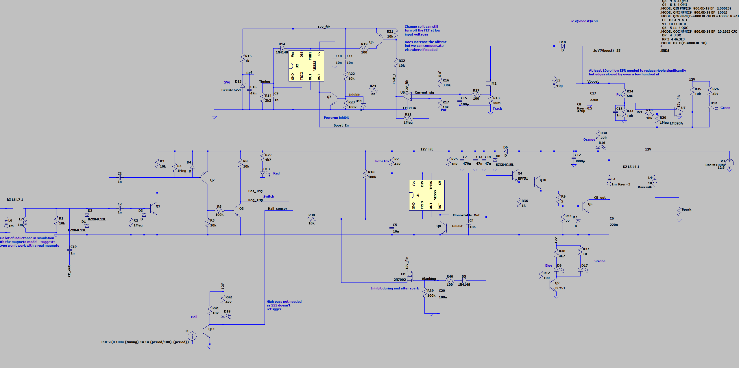
There's quite a bit going on, but essentially it can be broken into the following sections.
Boost supply
This is a constant-off-time, peak current controlled, boost regulator built around an LM555 (well, one half of a 556 actually) and an LM393 comparator. Why not a realy power supply controller? Mainly that there wasn't one in the junkbox. M2 is turned on until the current in the sense resistor (in fact a few lengths of stripboard track) reaches the threshold set by R16 and R17, and trips the comparator which then turns the output off via Q6, R19 and resets the timer via D1. That stays off until C9 discharges via R14, and the 555 turns the output back on. This then has simple hysterestic control of voltage via the other comparator, which I have set to around 55 V. Note the negative side of the output capacitor is connected to Vin, which eliminates the uncontrolled inrush current that would normally be associated with this topology. L5 is around 20 uH and taken from a PC PSU (as was diode D10). The end result is a boost converter that runs at full poweer in continuous conduction mode until the Vboost capacitor is full, and then shuts down, blipping occasionally to counter leakage through the feedback network and the indicator LED D16.
Trigger input
Separate positive and negative input circuits are provded and selected by a switch. This is necessary so that the circuit can be completely insensitive to the other edge, else it might trigger when the magneto points close. Note L6 and L7 are modelling the magneto and C19 was modelling parasitic coupling.
Monostable
A very standard 555 monostable is used to create a 0.5 ms wide pulse. Normally this would be too little dwell time to build up energy in the ignition coil, but the use of the boosted supply allows this to happen much more quickly. This pulse had to be kept short as it directly delays the spark - the main downside of this approach over a CDI one. I did initially toy with an approach with a more conventional longer dwell time, but that requires a feedback loop that tracks RPM and guesses when the right time to start charging the coil is, and it was hard to get right.
There is also a lockout circuit built around D5 and M1 which inhibits another trigger until around 5 ms after the spark has happened - this is necessary to avoid the device constantly triggering itself from high frequency noise.
Coil drive
About 1.6 A of base current is thrown into Q5, which is a BUS13A power transistor. Q10 is probably overkill, but gives the 55 an easier life, allowing the use of a CMOS device if desired.
Strobe
An extra transistor, Q9, drives a high power external LED to use as a timing light.