I built this around 2017 but have only just gotten around to writing it up. Essentially it is a 4-channel load controller for optimising the use of domestic grid-tied solar. The four loads can be assigned different priorities and are modulated to servo the net exported energy to zero so all generated electricity is used internally. It takes advantage of the 1 Watt-hour (3600 Joule) “dead spot” that electricity meters (in the UK at least) have by design by tracking a “window ” of 3600 Joules and modulating the loads on and off when they reach the edges of the window. In fact there are four priorities to which the loads can be assigned and each has 1/4 of the window so any one load actually oscillates around 900 Joules. On a mechanical meter this rocks the disc back and forth by less than one turn, on an electronic meter it does the equivalent with an internal buffer, in both cases a few hundred joules is repeatedly “borrowed” from the grid (as the loads are generally greater than the generation) and then returned a short while later.
I suspect most people would probably do this in software, but I thought it interesting to do it all analogue. A voltage signal from a simple resistive divider is buffered and used to feed one input of an analogue multiplier, a current transformer generates a voltage across a burden resistor which is then amplified and fed to the other input. The multiplier outputs a signed voltage proportional to power, pretty much independent of how ugly the current waveform is, and this is fed to an integrator with a low-leakage capacitor. This integrator tracks the window and a bank of four comparators switches switches the loads. Each comparator has a little less than 1/4 of the window in hysteresis, and one of four thresholds set by selecting load priority. The loads are switched by large triacs which are triggered by smaller opto-triacs.
There are a few extra features to the circuit, it has an overheat detection which shuts down all of the loads, and a remote override which allows a load to be forced on even if it would result in net power import. This is actually the main reason for the overheat detection as it becomes possible to turn on all loads (a total of up to 60 A) simultaneously - something that wouldn't happen normally as max solar generation is only 16 A per phase. The override circuit has its own isolated power supply so that it can use external switch contacts, but a powered source is possible by moving some jumper around. LEDs are driven to indicate the status of the loads and also to indicate if the integrator has run into the rails implying net import/export.
Power supplies are kept pretty simple and transformer based, with long-life, high temperature electrolytics and low ripple currents to give maximum service life. Four supplies are generated, an isolated 5 V for the remote override and a +12 V, -12 V and +5 V for the main circuit which is neutral-referenced. There are a couple of expansion connectors with the power supplies and the various voltage, current, power and energy signal on to allow a future digital board that does monitoring and/or augments/replaces some of the control functionality. The main power channel measures net import/export, there is an auxiliary channel that measures solar generation - it's not needed at all for the controller but provides some extra signals to the< expansion connectors.
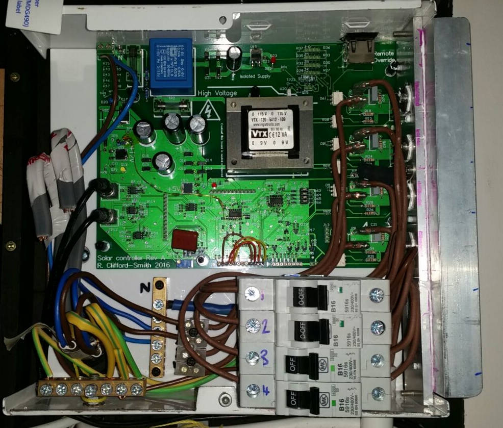
As this went straight to PCB without prototyping there are a few bugs which have resulted in hand-modifications but nothing major. Mainly this relates to a mistake regarding comparator common-mode input range, which was corrected by adding a low-power zener-regulated supply at ~16 V. The whole thing has been built into a metal box with four 16 A MCBs for the loads and front-panel switching for the priorities. So far only two of the load channels have been used but more will be added.
In operation the highest priority load is turned on first, and then if solar output is more than that load additional loads are switched in, with the lowest priority load being switched on and off to maintain the zero average input power. In practise most of the time the generation is smaller than the loads so the highest priority load is switched on and off until it stops drawing power (e.g. cutoff by its internal thermostat) and then that is left on and the next load switched in. If some uncontrolled load is added then the controller acts in the same way as a reduction in generation, shedding the controlled loads to try and maintain zero import.