A joint project between myself and Mark (Larry)
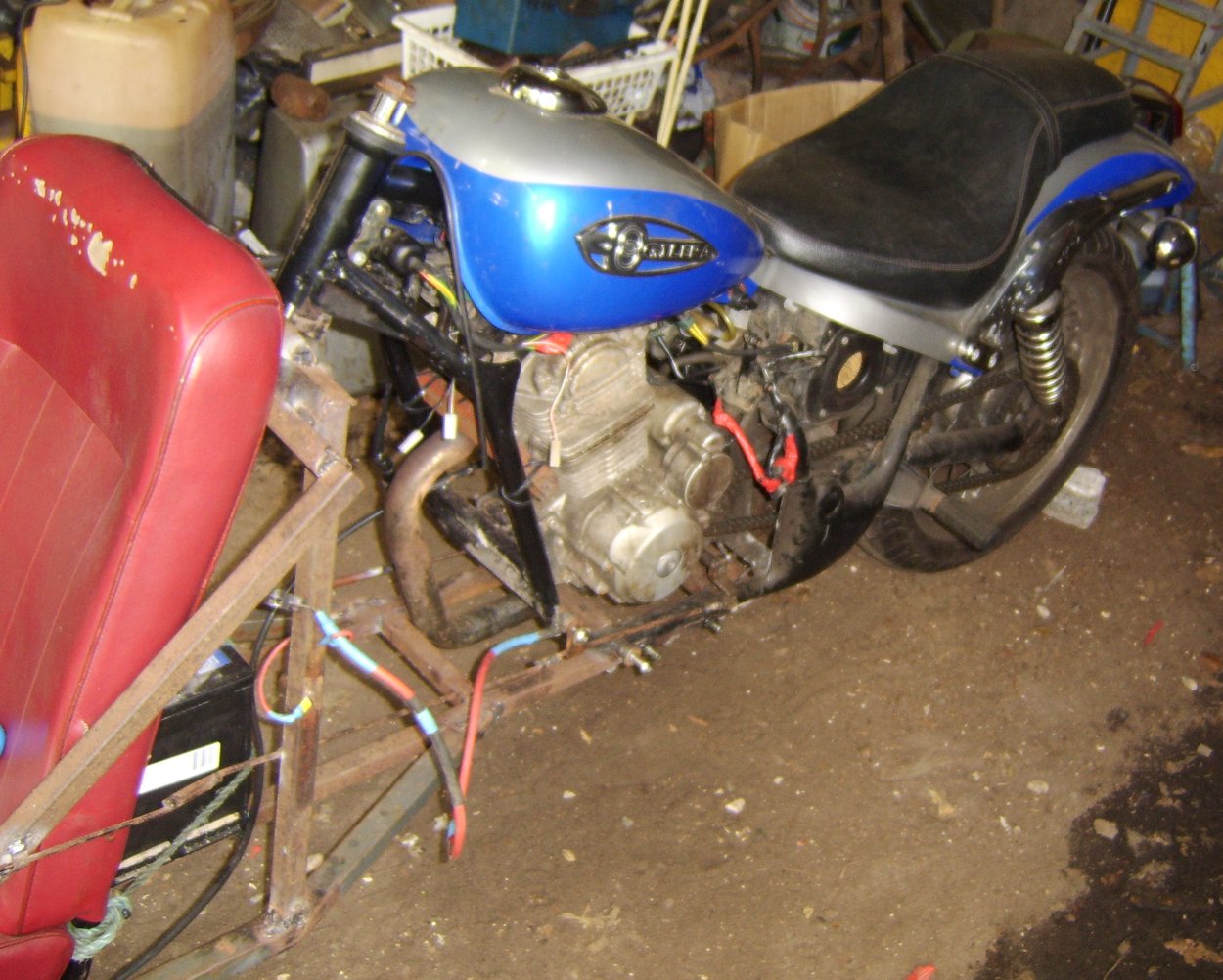
The idea of building a trike had been floating around for some time and included a number of different designs. The current once was born after finding a motorbike dumped in the woods near where I live. the bike in question is/was a Gilera Cougar. The trike is the other way around to what would normally be expected i.e. with two wheels at the front and one at the back. At some point in the future we intend to build a normal trike. Some ideas for this are documented here.
All images on this page are low resolution versions. Click them for bigger versions.
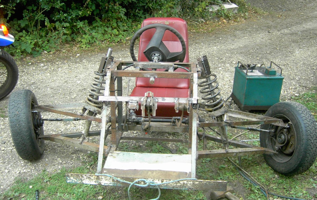
The main structure of the trike is steel box section and angle iron. No structural metal was bought for this project, it was all acquired through various means. (scrap that was laying around the farm, old roadsigns, anything that was free). In the photos below a basic frame has been constructed of 30mm heavy walled box together with a seat we got out the back of an old van. The seat has a very strong tubular frame which forms part of the chassis of the trike.
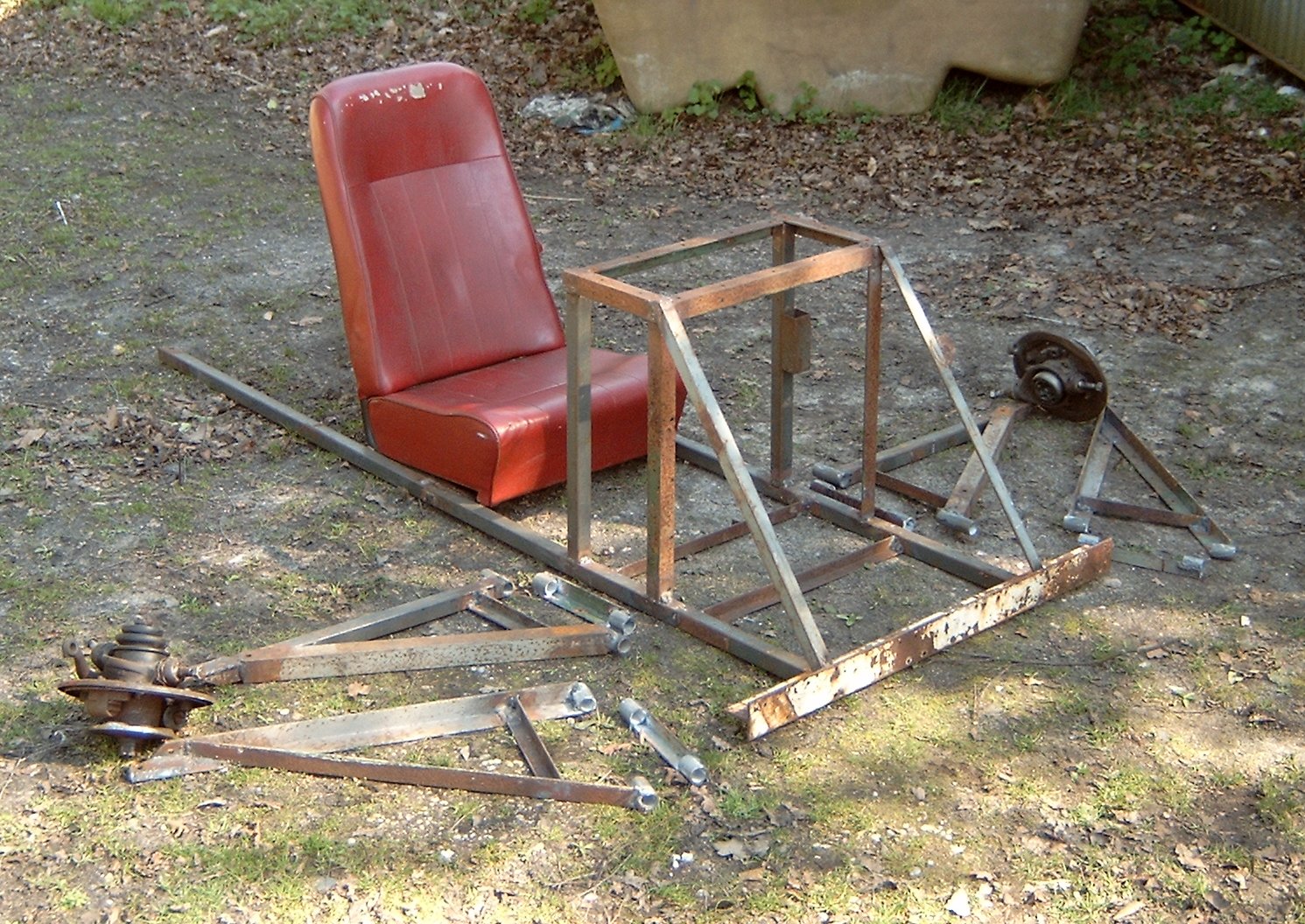
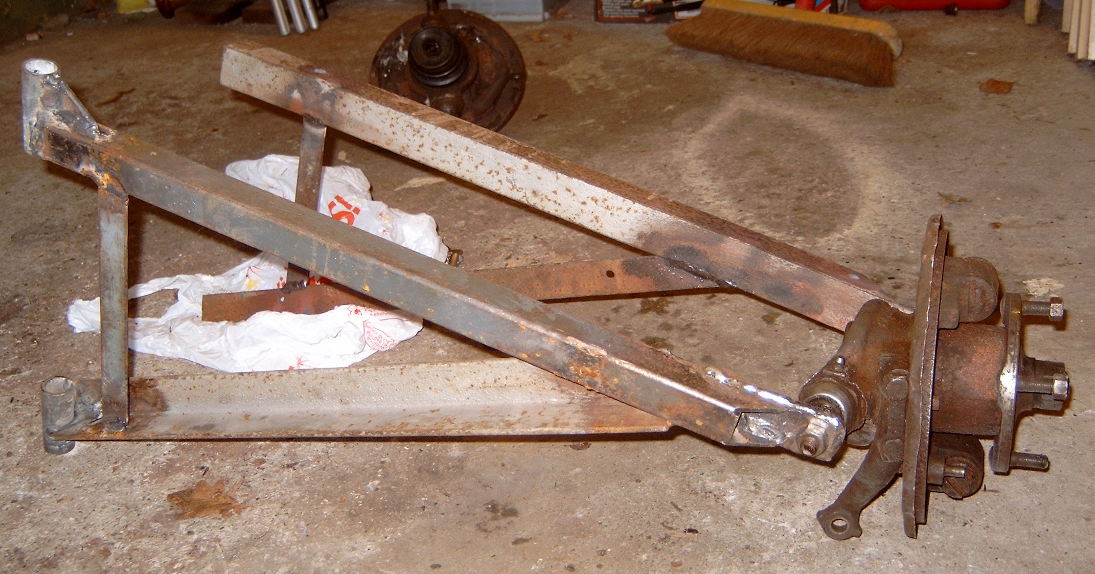
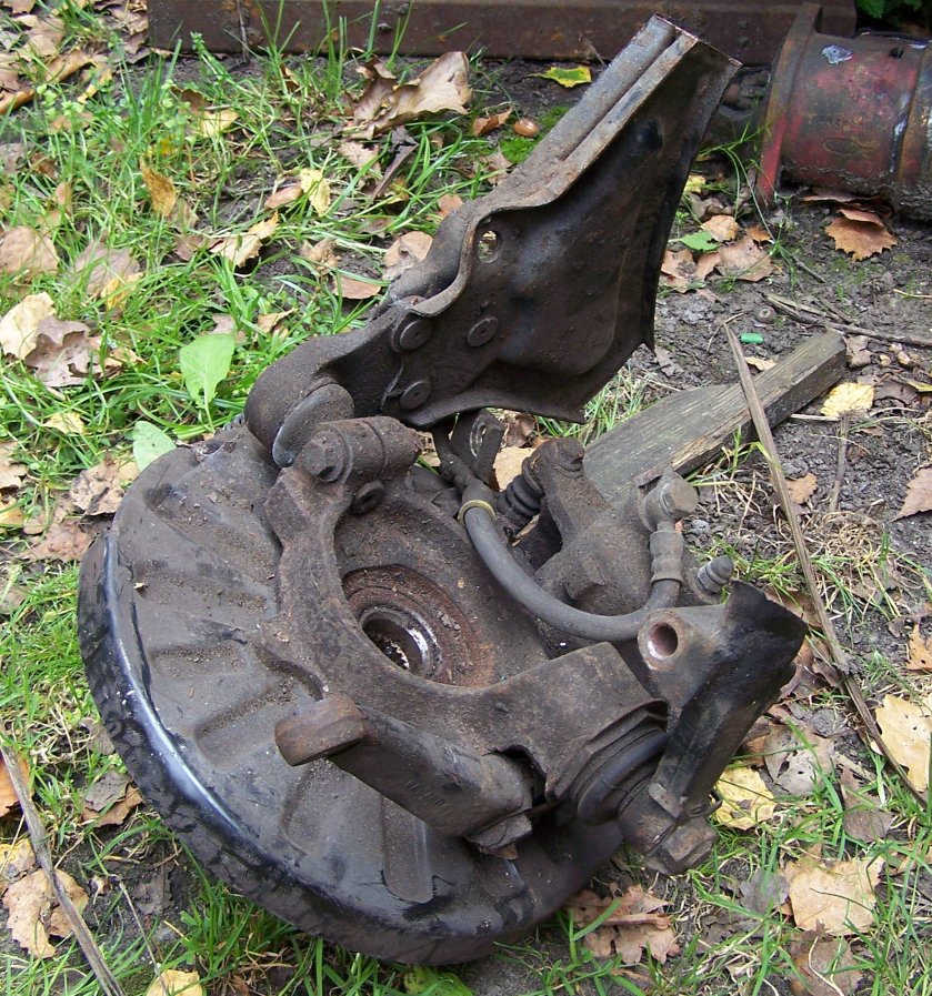
The second image above shows the suspension arms before being attached to the frame. They have been made to fit a pair of front hubs from a mini (bought for £20 on eBay). The arms are made from extremely thick box section and angle and the ends where they bolt to the hubs have been re-enforced with several layers of welded plate. The holes themselves are stepped to take the tapered ends of the pins on the hubs. At the other end of each arm is a pivot consisting of short lengths of iron pipe through which a length of 20mm steel bar can be put. This bar joins the arms to brackets which will be welded onto the frame of the trike. These brackets can be seen in the first picture before they have been attached.
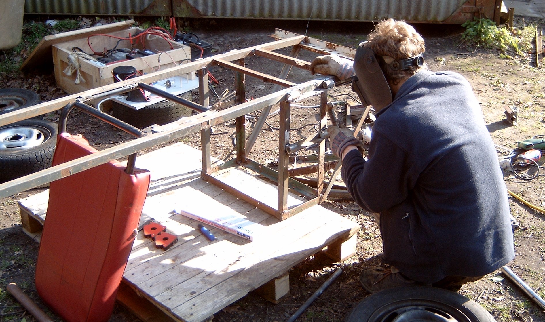
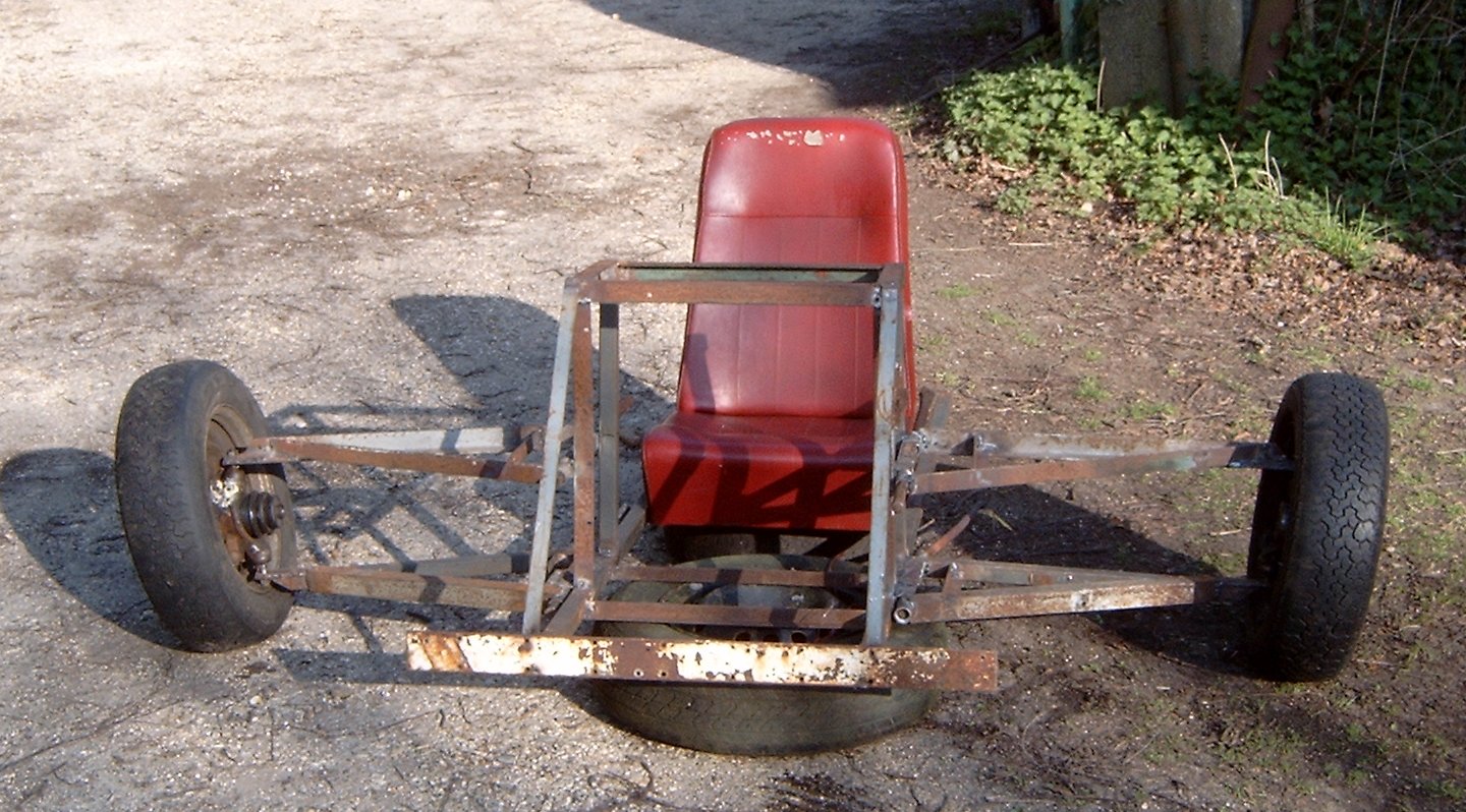
Above you can see the mounting brackets being welded to the frame using the battery powered arc welder. More on that and the reason for its use can be found on its dedicated page. The second photo shows the trike with the suspension arms pinned to the frame and the two wheels (these are in fact metro wheels). The wheels appear to be at an angle because they were not bolted on when that picture was taken, it took a long time to find some suitable wheel nuts. At this point the back end consists solely of two parallel pieces of box section. This will later become the mount where our home-made frame attaches to the bike.
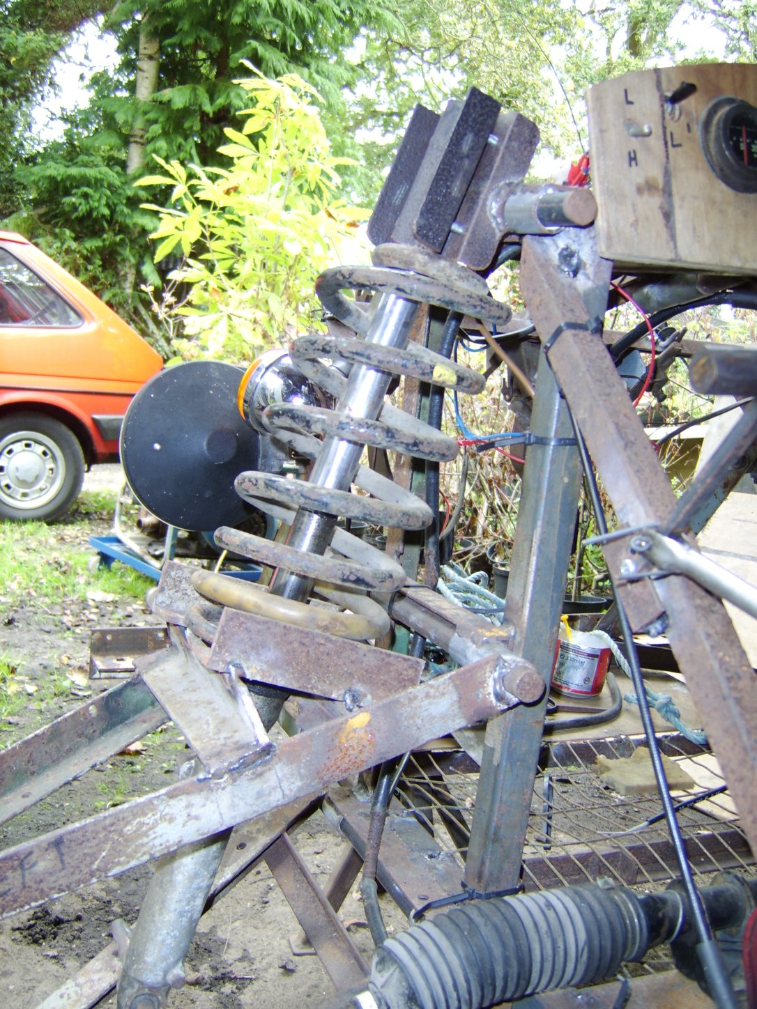
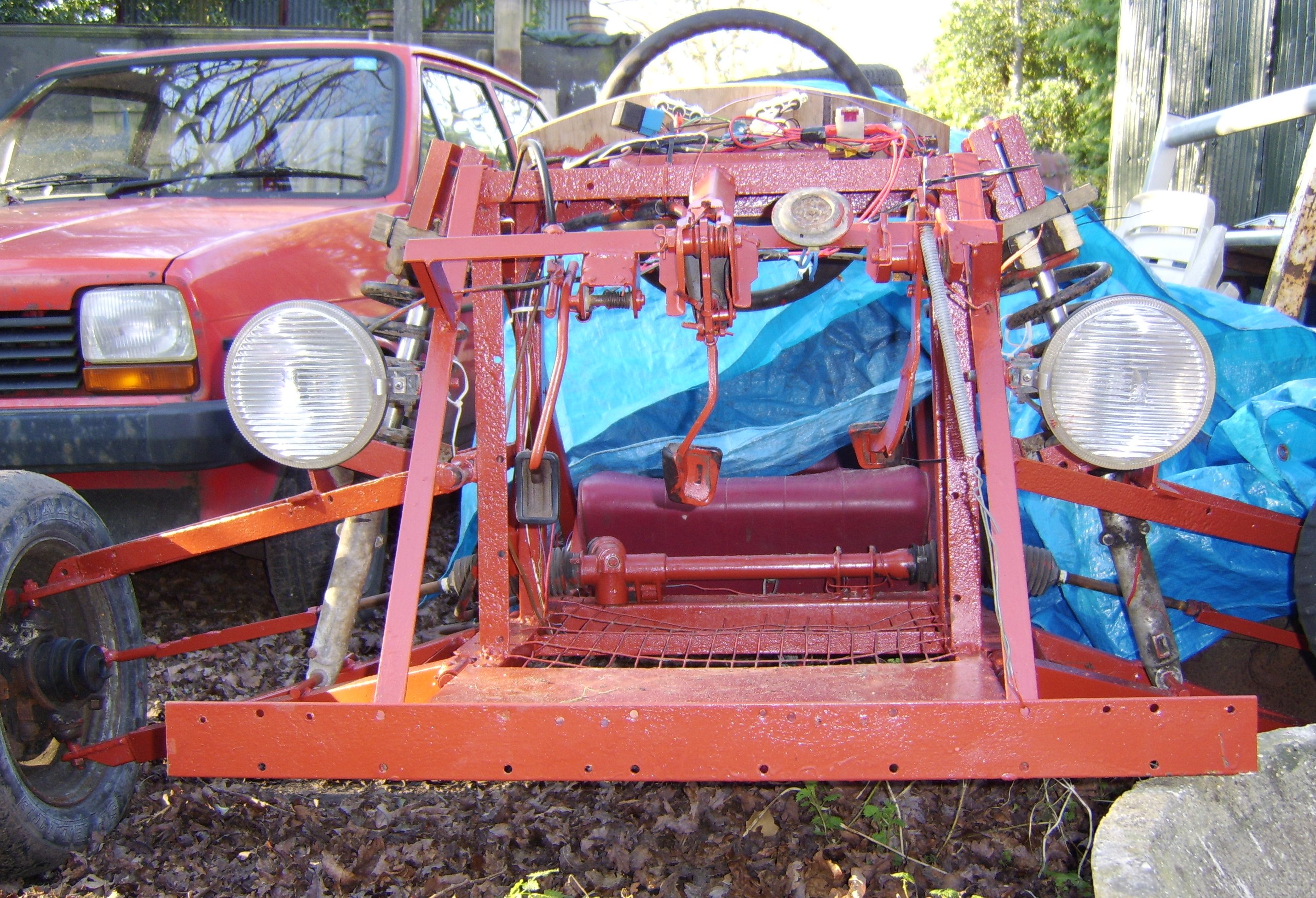
Suspension consists of two shock absorbers from another motorbike (also found dumped in another piece of local woodland) and two springs from a Ford Cortina. The springs take the majority of the weight and the shocks act to damp the movement and prevent wild oscillations. The first photo below shows the current (January 2007) suspension. This works but is much too soft so at some point this will be altered in order to compress the springs much more.
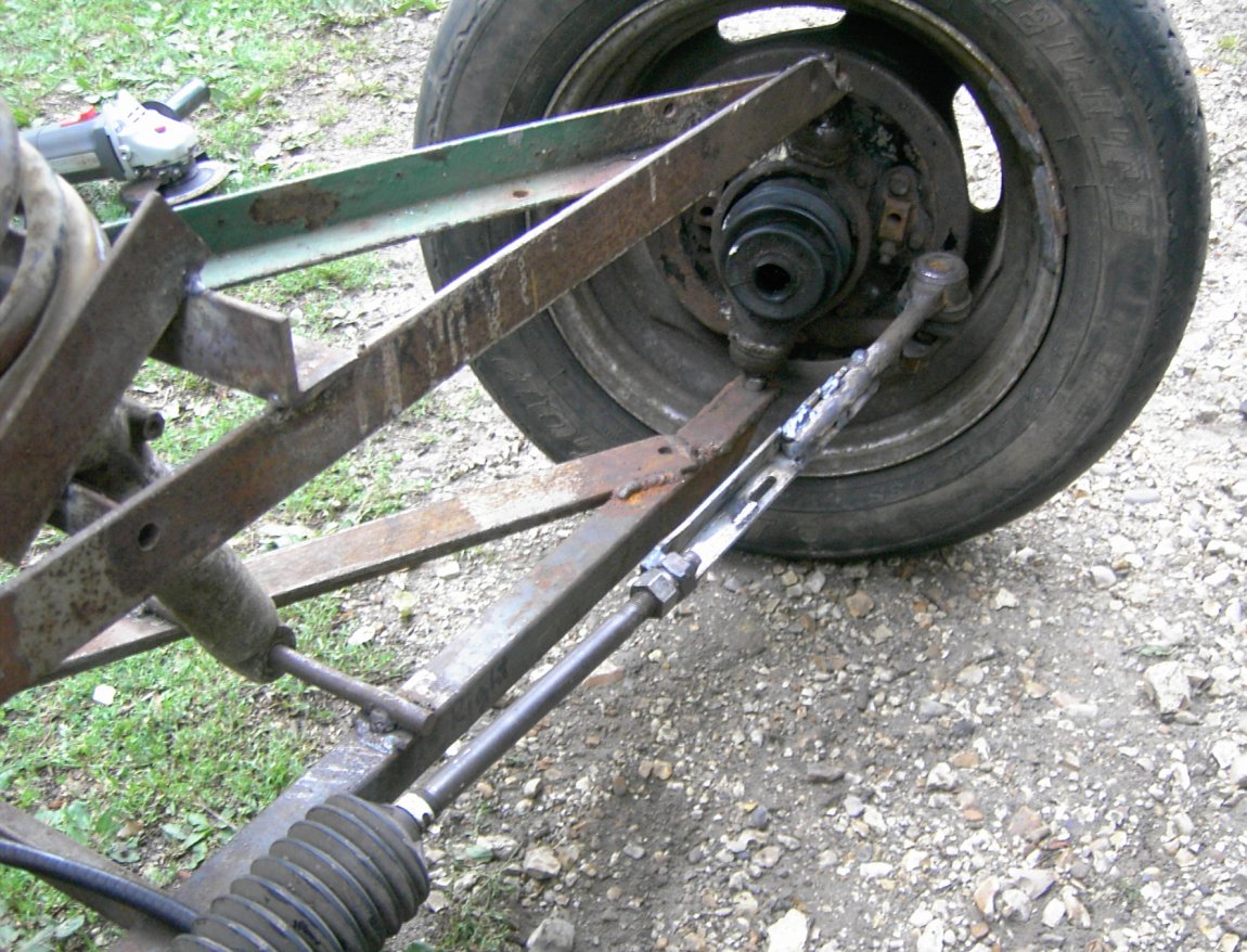
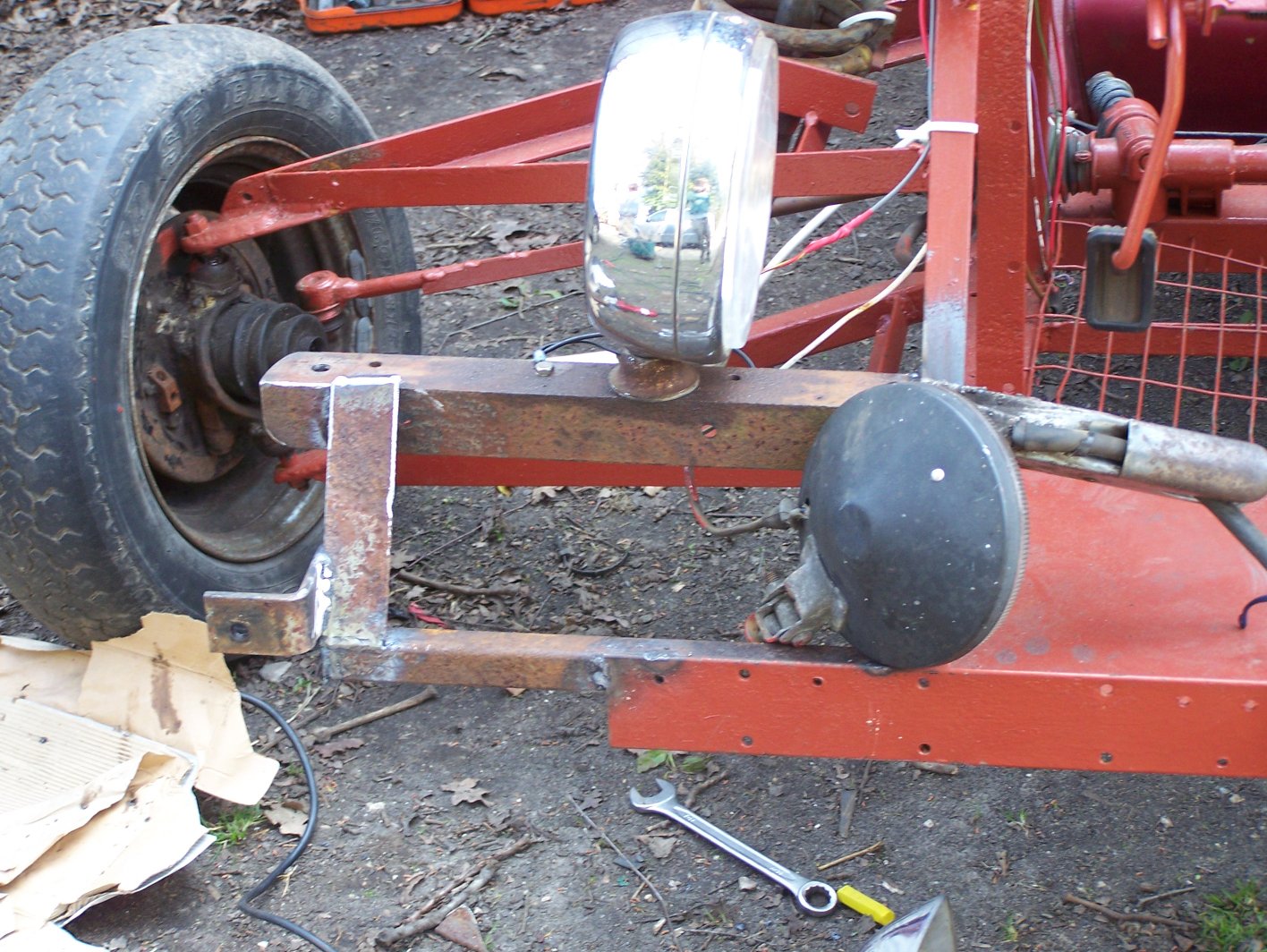
After the suspension the next thing is the steering. A Ford steering rack was found in one of the sheds and bolted to the chassis of the trike. This was then connected to the hubs as shown in the second of the above photos. This join is fully adjustable to allow the steering to be lined up. We had some problems working out how to connect the steering wheel to the rack and it was eventually decided to do this with cables (there was no other practical way). The steering wheel is from a Vauxhall Cavalier and is attached to a steel shaft. A flexible cable wraps around this shaft and around a short piece of tubing welded to the rack. Between these two points the cable passes through a sheath that formally contained the handbrake cable on a van. This is much better than the original idea which was to pass the cable through small pulleys, seven of which would have been needed.
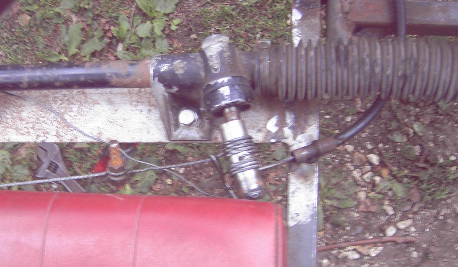
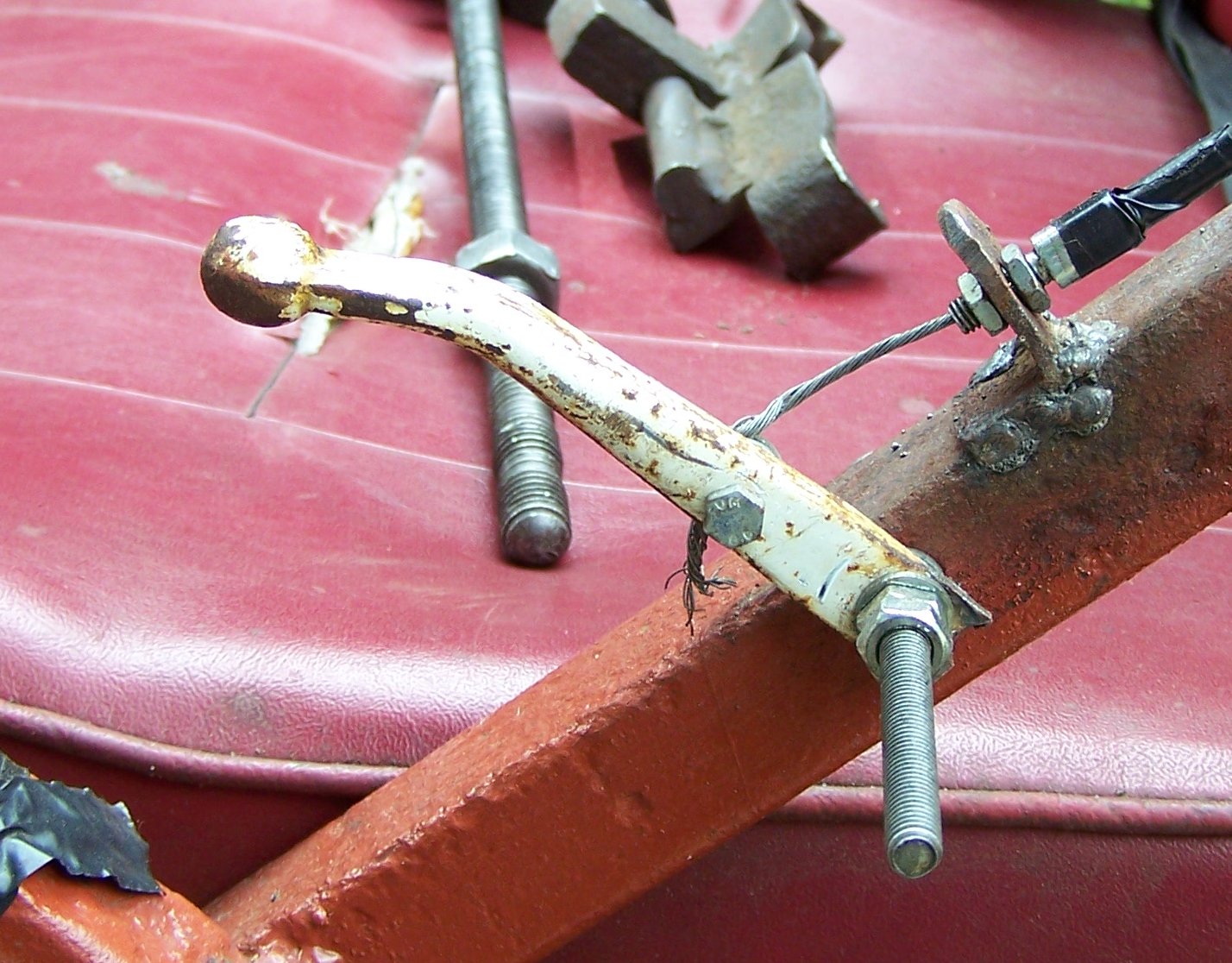
This cable steering system can been seen in the two images below. The small chunk of metal welded to the steering wheel end and the piece of box at the other end (which is actually curved to fit around the shaft) both act as guides to keep the wire in the right place and prevent jams. This system is by no means perfect - it needs tightening occasionally as the cable stretches and is also fairly noisy, although most of that is due to a 'temporary' wire guide piece at the bottom near the rack (visible in the second picture). Temporary in this case means until we get around to changing it. The two ends of the wire are joined with a piece of threaded rod, the wire passes through a hole in this rid and nuts are then tightened against it to trap it in position. Steering is adequate provided it is well greased.
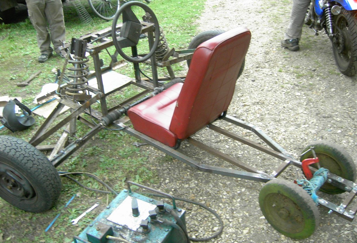
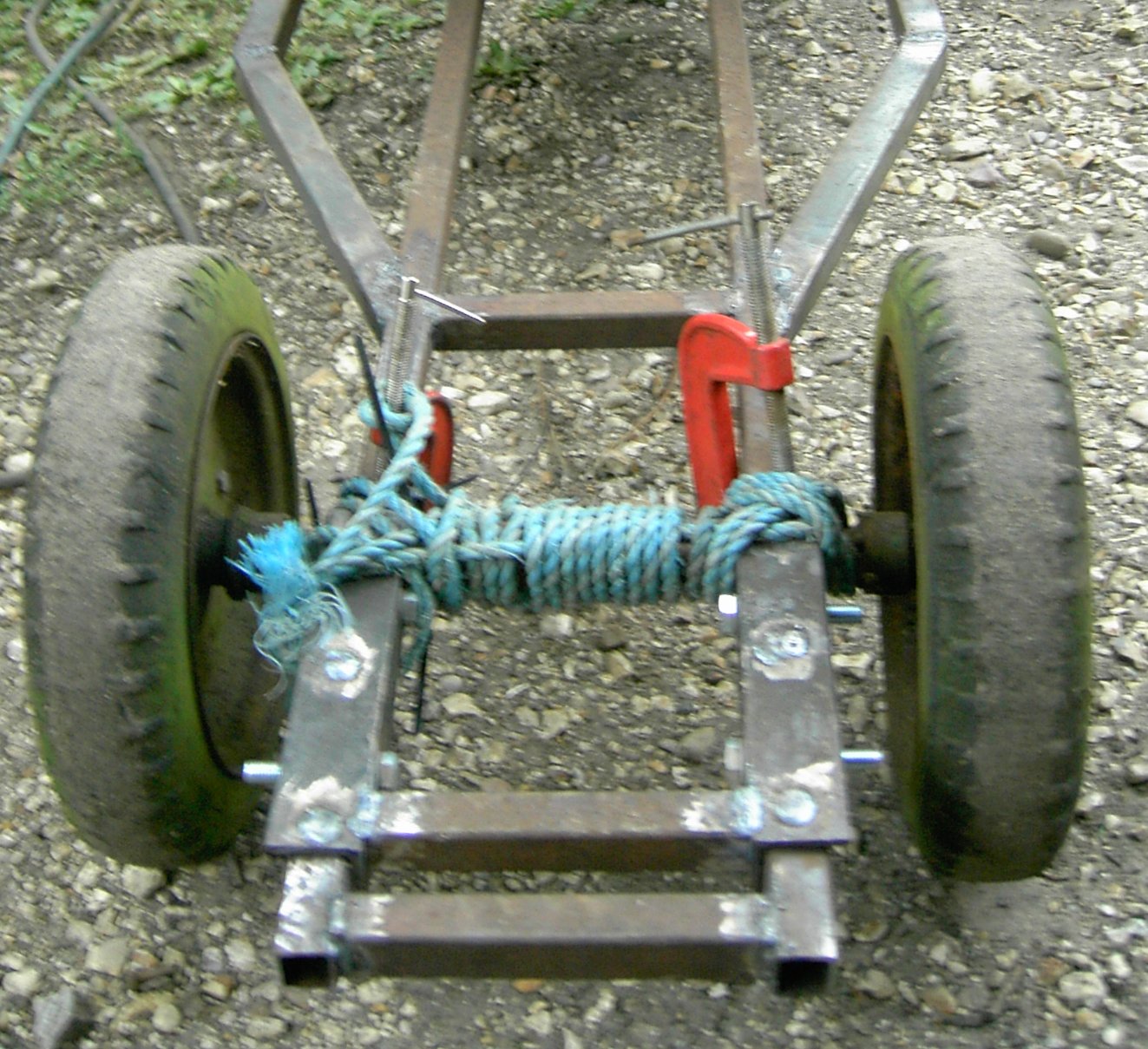
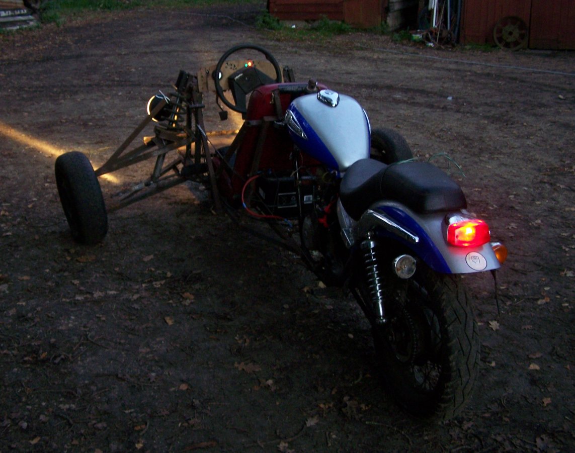
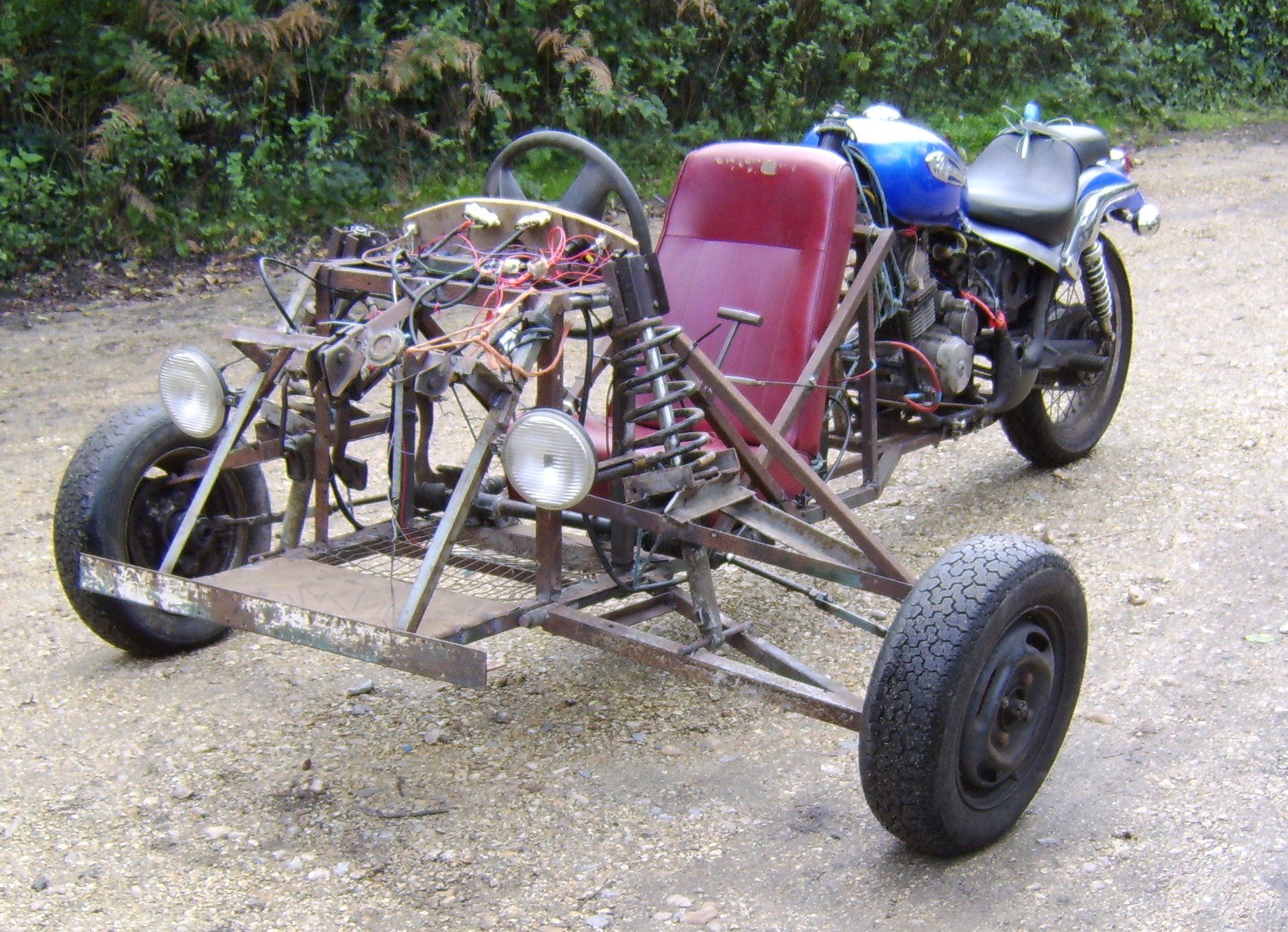
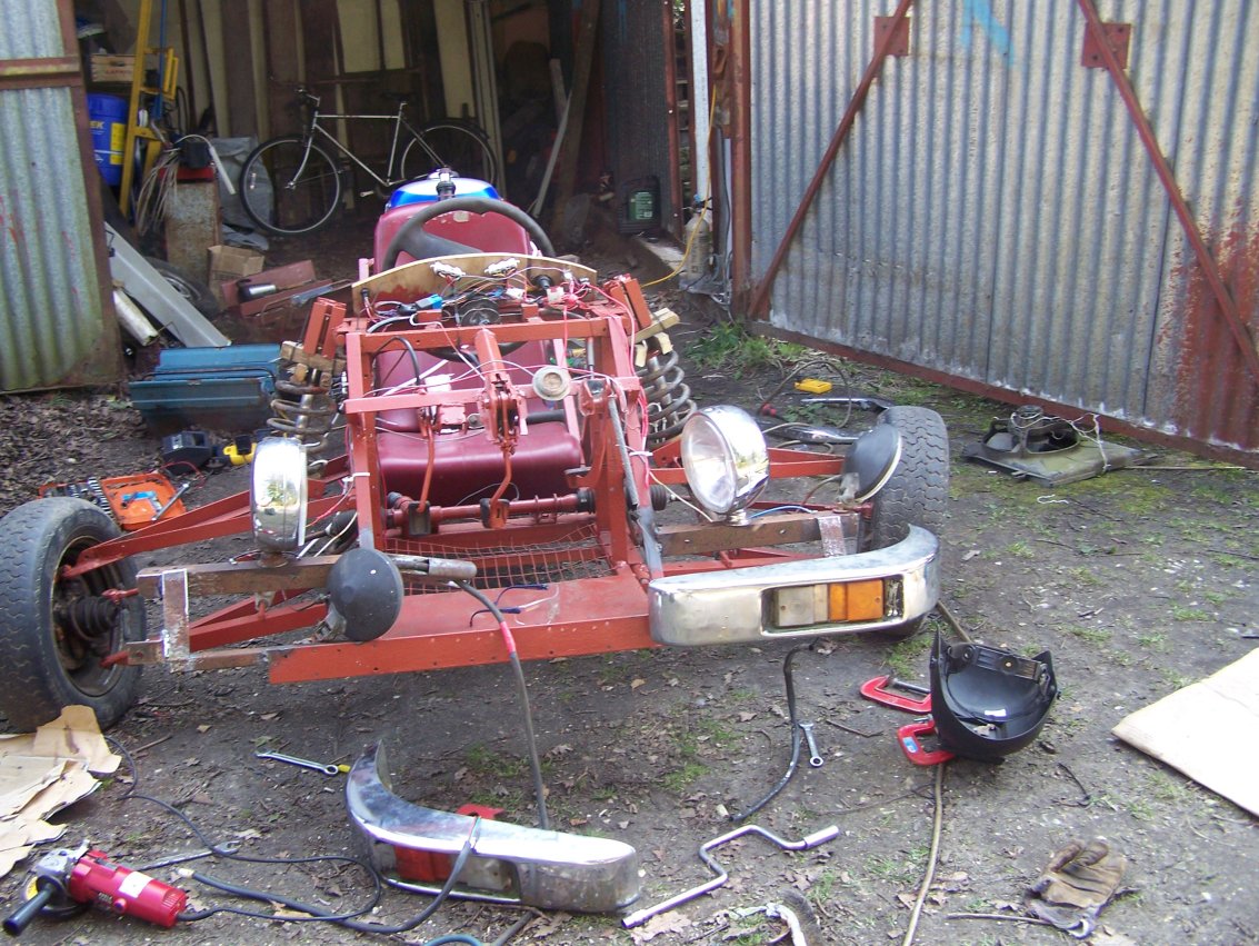
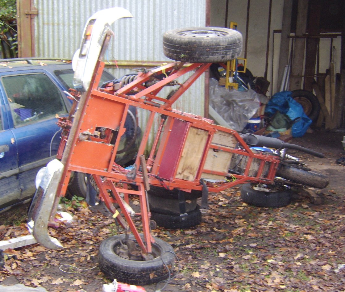
With all that completed, the wheels bolted on and a few other minor additions such as the pedals and the sheet metal floor the trike is starting to look like something. By this point we had also started to make the join between the bike and our front end. The photos show that nearly completed. The two small wheels at the back are just some we found lying around and were attached using clamps, rope, and cable ties to allow us to ride down the hill on it. While fun we found that with hardly any weight on the back it was almost impossible to steer (temporarily solved by having someone stand on the back during the ,er, 'tests'). This was mainly done for fun but it showed the steering to be workable and also some of the inadequacies of the current suspension. Also visible in the pictures below is edge of the bike and it can also been seen that the power has been fixed hence the use of a more conventional welder.
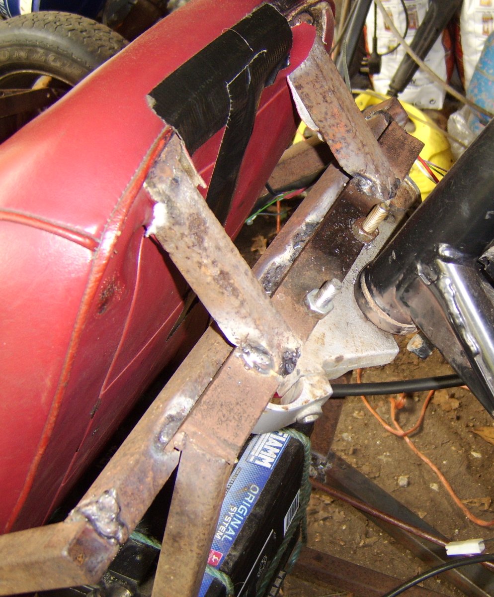
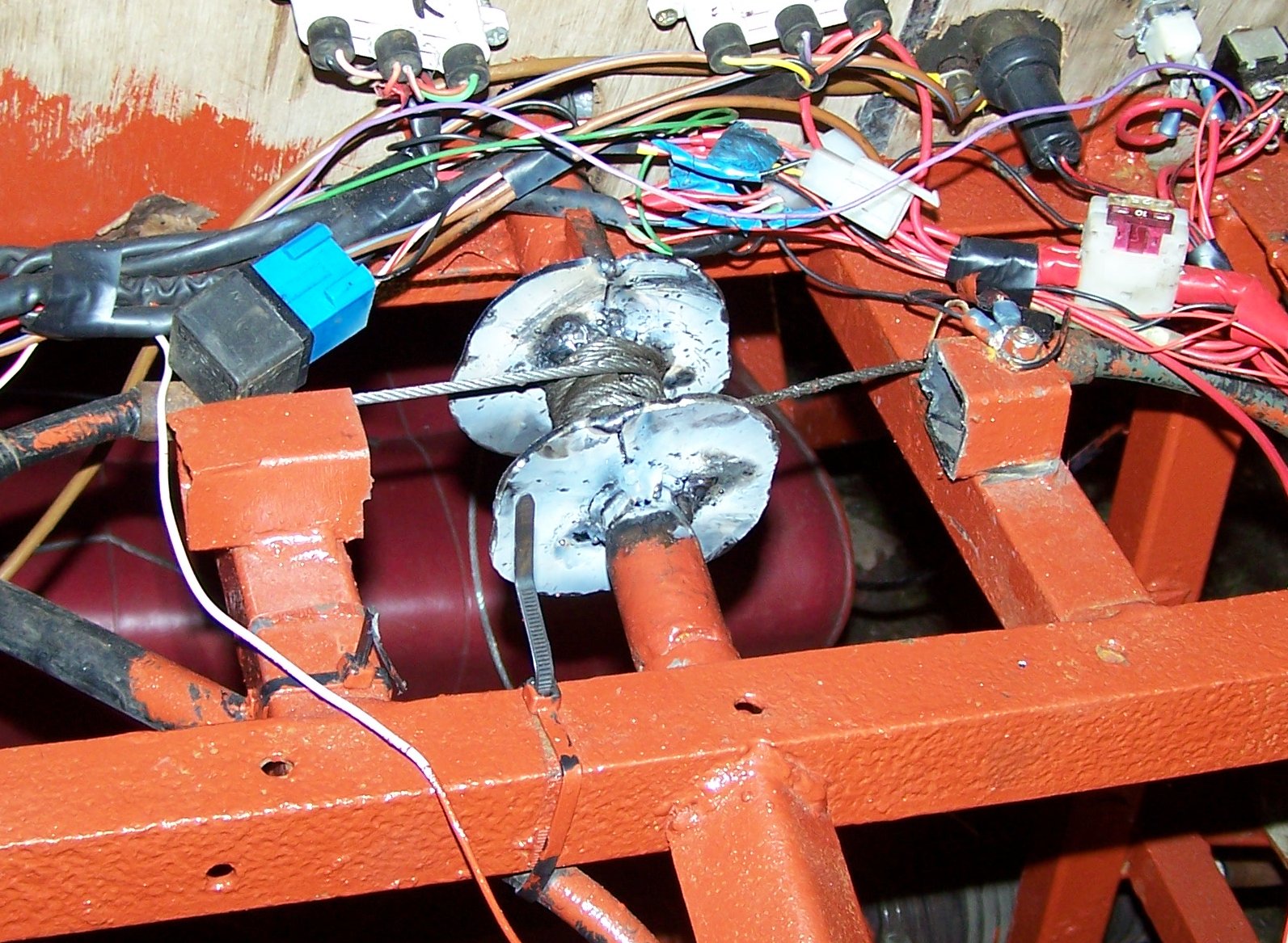
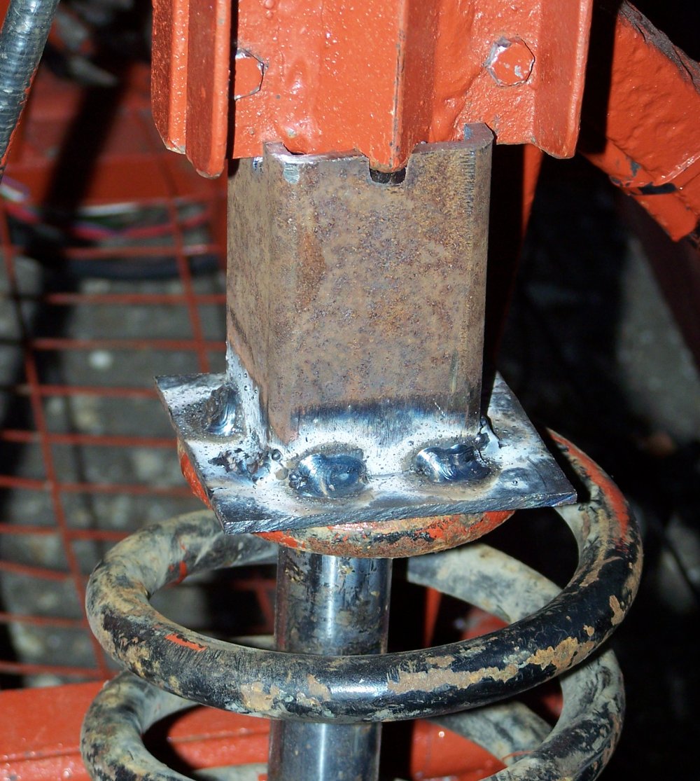
Having had some fun messing around with the trike like this (at one point we were riding it down a hill and towing it back up with Larry's fiesta) we finally got around to working on the attachment to the trike properly. This consists of two parts: the first a join at the bottom (pictured above, close-up below) where a small angle iron bracket is bolted to the back end of the trike's frame and then carefully welded onto the frame of the bike. The second is at the top behind the seat. It is another bolted join to the bike which then attaches to some more of the trike's framework. This has been done so that the two can be later separated should we ever decide to (although admittedly it would be a lot of work). The bars that go into the back of the seat are actually welded onto the seats tubular steel frame. as mentioned earlier this frame is very strong and forms a structural part of the trike. About this time we also replaced the sprocket on the rear of the bike which had been extremely worn when we acquired it. To start with we had just put the worn sprocket on the other way around so that the chain did not slip as much over the worn teeth but with the extra weight on it we bought a replacement from http://www.motorcycleproducts.co.uk
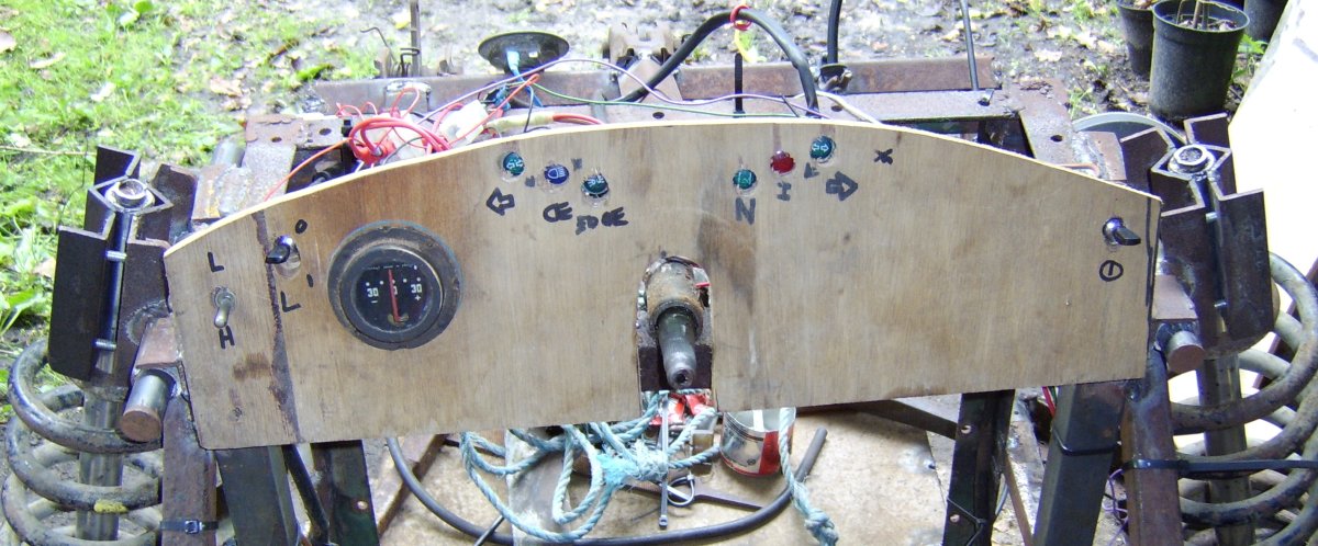
After the two halves were joined it became a question of connecting up the controls and adding all of the little things. Cables connect the pedals to the appropriate controls on the bike, at the moment the brake connects only to a drum brake on the rear wheel but future plans include connecting this to a master cylinder so that it can also work the hydraulic brakes in the mini hubs at the front. Major changes were made to the electrical system; a 70 ah battery was added to allow easy starting after several months of disuse and allow the use of the new headlights without the engine running. This was placed behind the seat and connected in parallel to the existing motorbike battery. The key switch on the bike is left permanently on and all power to the trike now passes through a relay controlled by a switch on the dash. The current dash is in fact temporary, made out of plywood as a place to mount all the electrical stuff in preparation for a test drive. Its replacement will eventually include an electronic speedometer and other stuff.
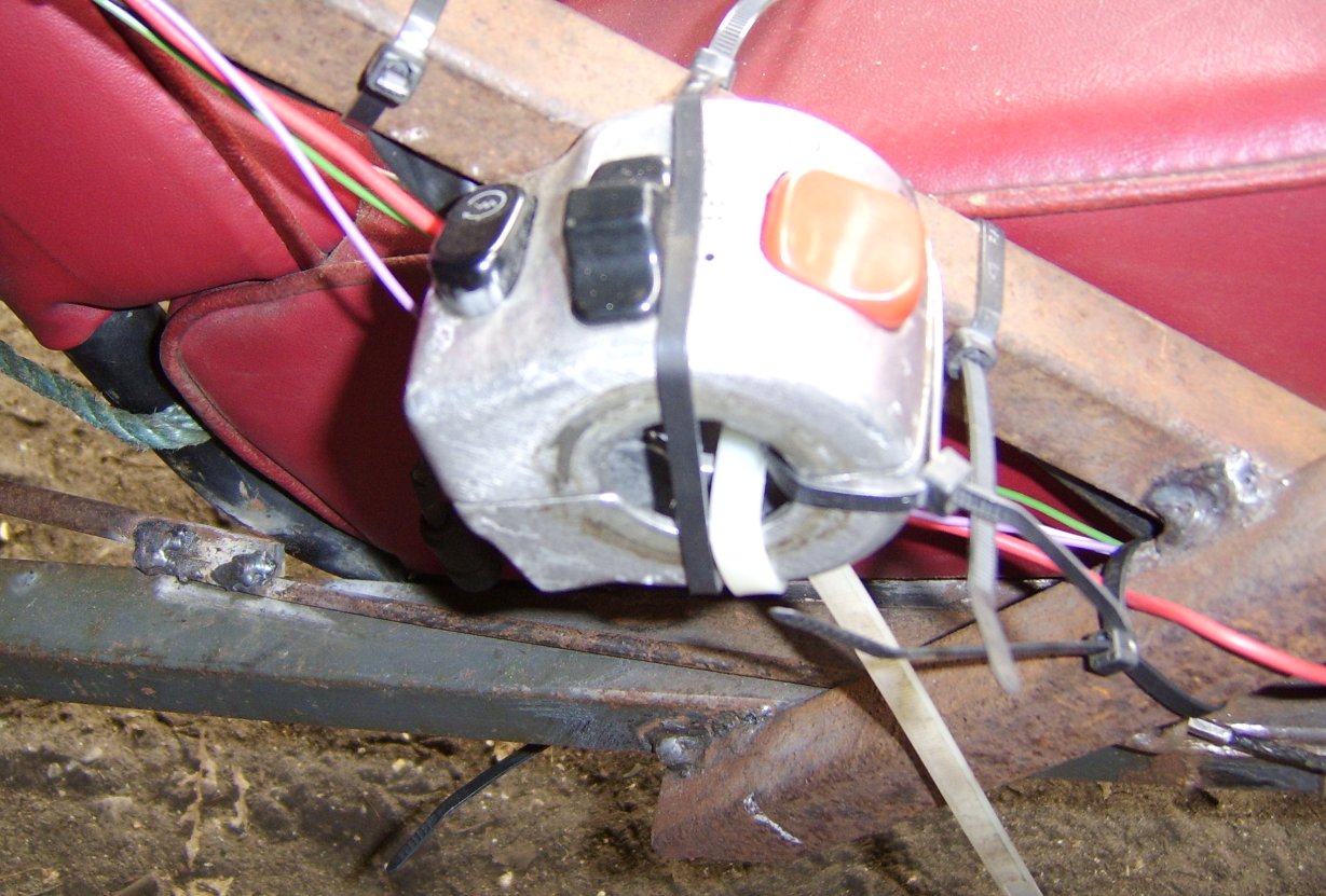
At this point it should be noted that much of this was being done a few days before I went to university 100 miles away in Exeter and Larry went back to college. This being the case we wanted to get as much as possible done while we had the chance and much of this electrical stuff was done outside of the shed in one night working from a couple of large halogen floodlights. We really wanted to take it for a test drive before having to leave it till Christmas. In the end we used more cable ties to fix the original starter button to the frame near the seat and at around 11PM the trike moved under its own power for the first time ever! We drove it around for a bit, tidied up, and finally went home at about 1AM.
Our short test drive revealed several problems, many related to sticky and badly adjusted throttle and clutch linkages. These were later solved leaving only the suspension. Where the suspension needs tightening the trike is very low to the ground, beyond the normal limits in which the suspension was designed to operate and this makes the steering awkward and hard to use. This has been bodged by locking the suspension with a pair of steel bars pending a modification that will improve this.
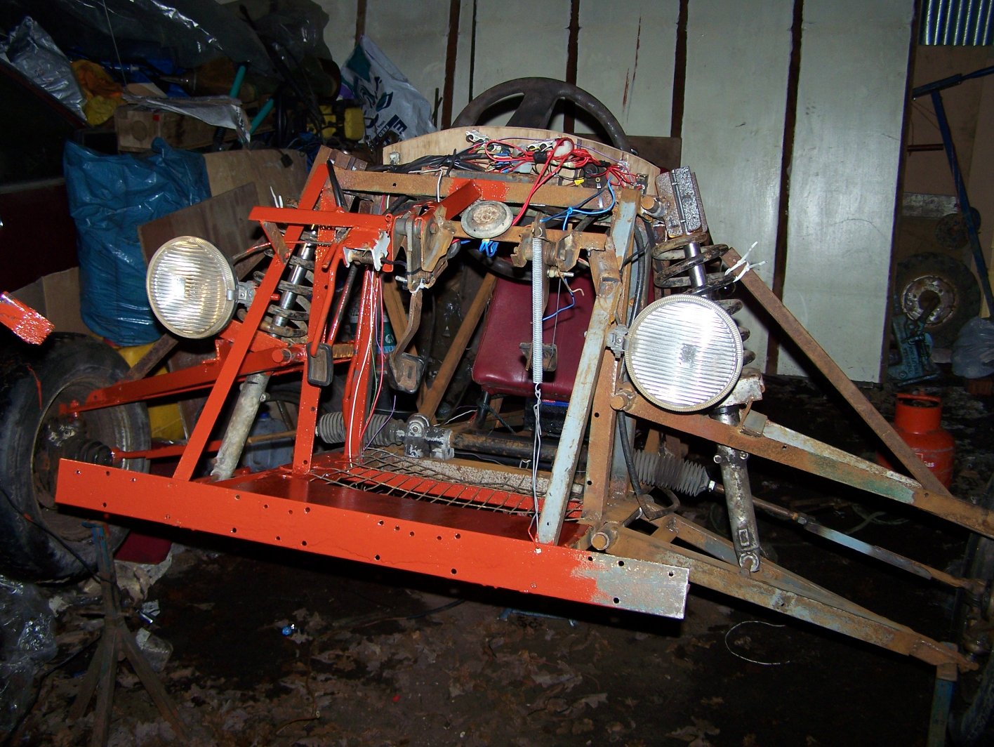
Since then various small changes and additions have been made but being winter it's hard to find the motivation to do any work on the trike. However we did find the time to paint the metal framework, mainly to prevent rust. We used red lead oxide primer which will eventually be re-painted in black. Despite the really horrible colour it does look somewhat better now that it has been painted as all the parts (except the bits we missed) are the same colour. At the time we were doing this the power had failed at the farm again and much of it was done with the aid of a pair of 12V halogen floodlights and, at one point, a gas torch.
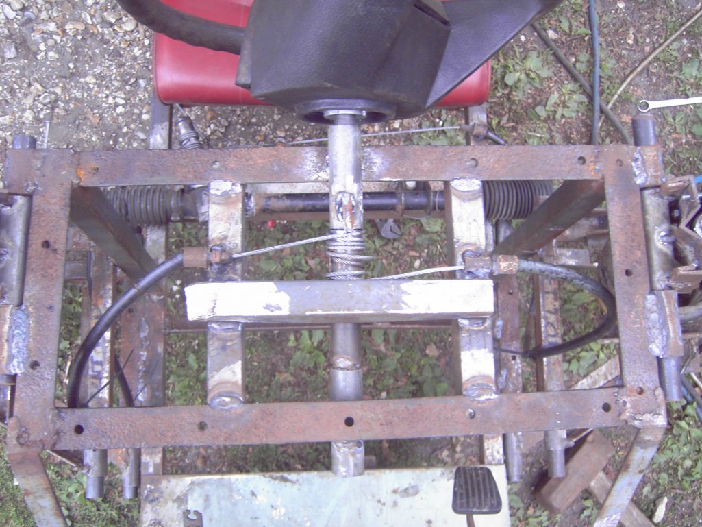
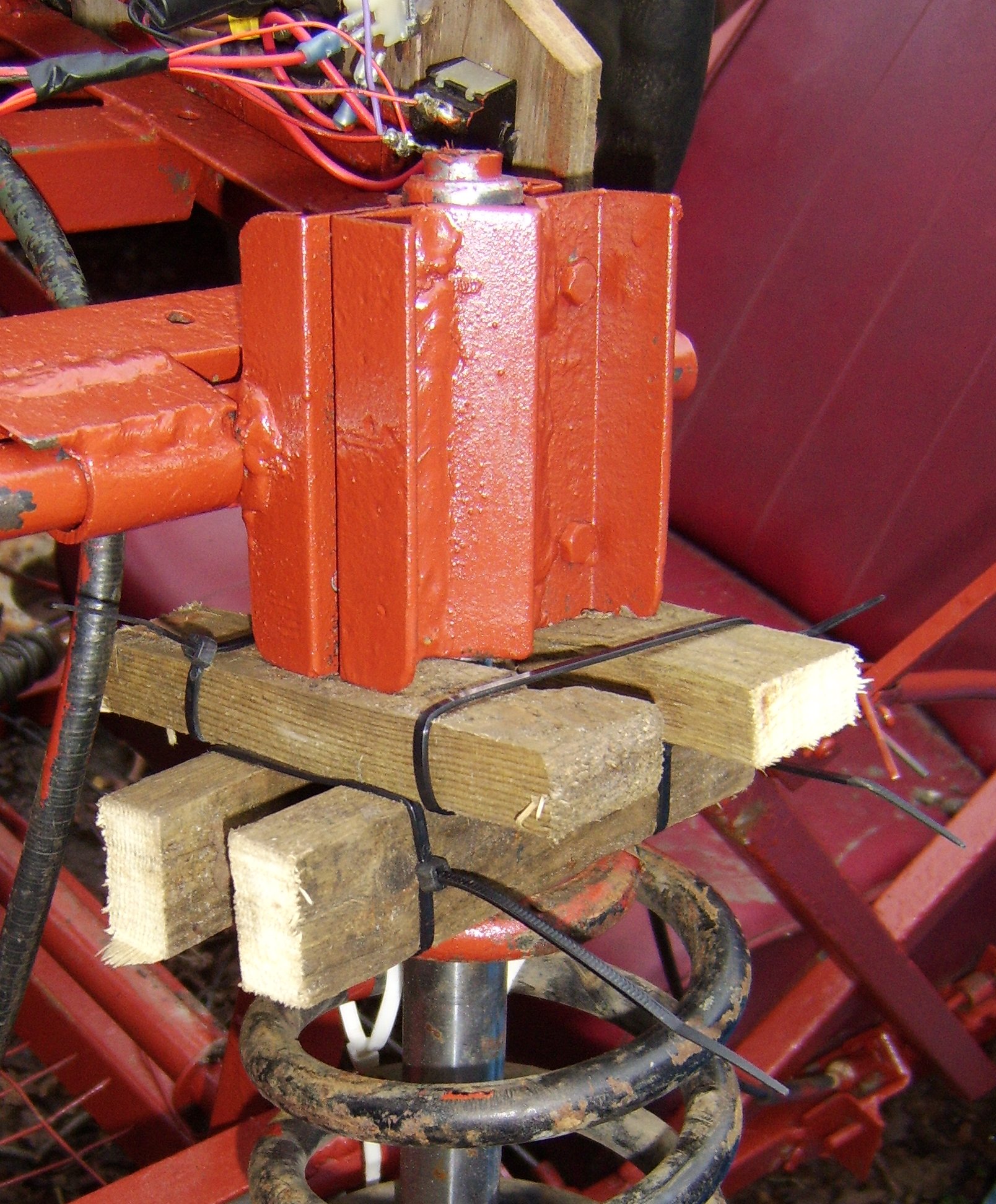
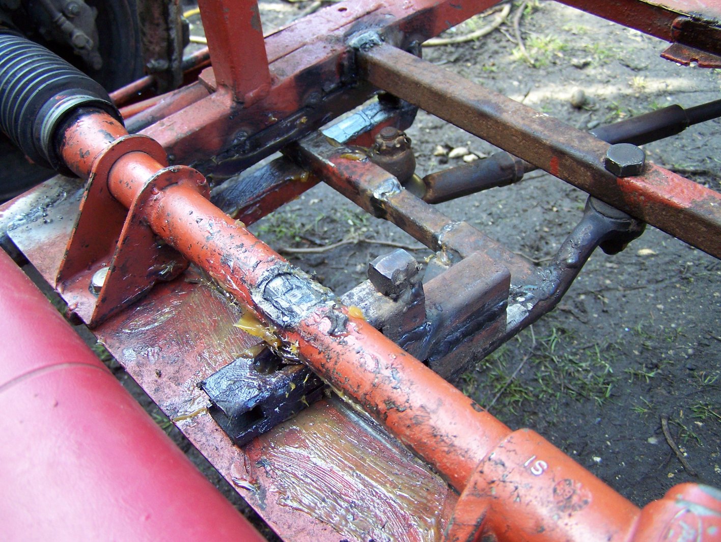
As of January 2007 we now have proper working suspension - even if it is made of wood. Larry compressed the springs and added the blocks as spacers. at some point we will probably replace this with steel but right now it is good enough and perfectly strong. This worked well in tests but we have since developed a problem with the steering - the wire got caught in a gap behind one of the guide pieces and jammed - its out now but the wire is a bit mangled. Should be a simple fix but we plan to change how that part works slightly to stop it happening again.
The first of the photos below shows the wooden suspension. The cable ties that are visible in the photo do not take any load - they are only there to keep the blocks from slipping sideways (not that it's going to happen anyway - the metal parts on each side will dig into the wood and hold them in place). The second picture is just another view of the trike after we'd finished painting it with the primer.
Easter 2007
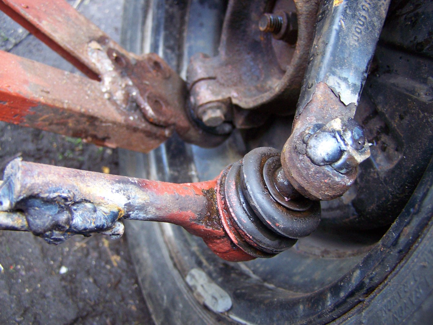
We now have slightly better steering - two giant 'washers' have been welded on to stop the cable coming off again. We're still using the original cable since it is only a little frayed but at some point this will probably be replaced with a new one (there are some nice stainless steel ones on Ebay). The modified steering can be seen in the first picture below.
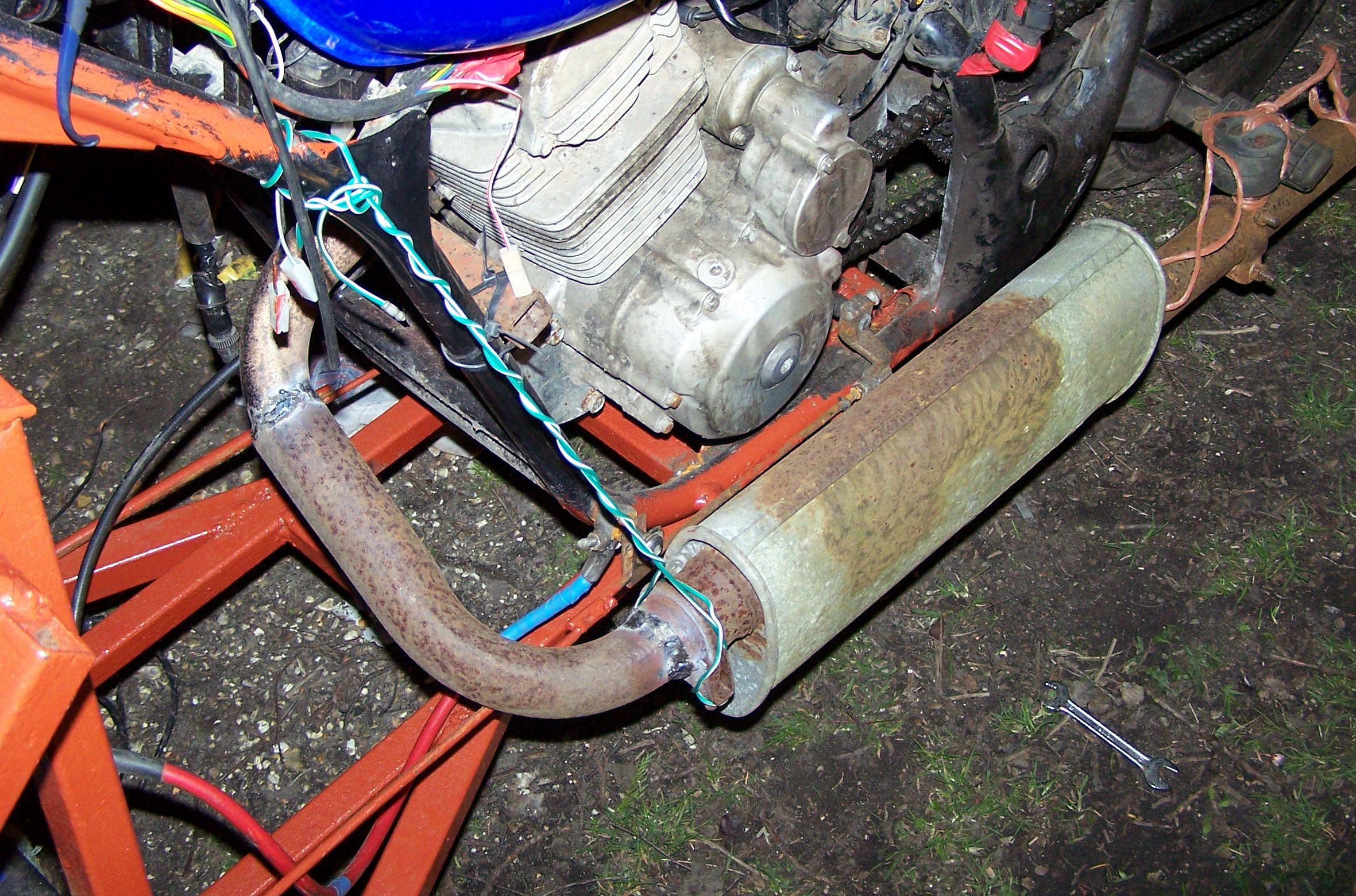
On the same day we also replaced the exhaust. The existing one had a very noisy loose baffle and was getting annoying in addition to not properly fitting around the new frame. The replacement is built up from a silencer and associated tubing that we found at the farm. Basically I cut it apart and welded it back together in a new shape to fit the trike as something to do while Larry was grinding some steel plate for the steering. Works fairly well and is a little quieter but the join to the engine is still slightly bodged since we have yet to replace the studs which sheered off a while ago. The new exhaust can be seen fitted to the trike in the above photo although it is currently held on with string - we plan to make some steel brackets to hold it in place soon.
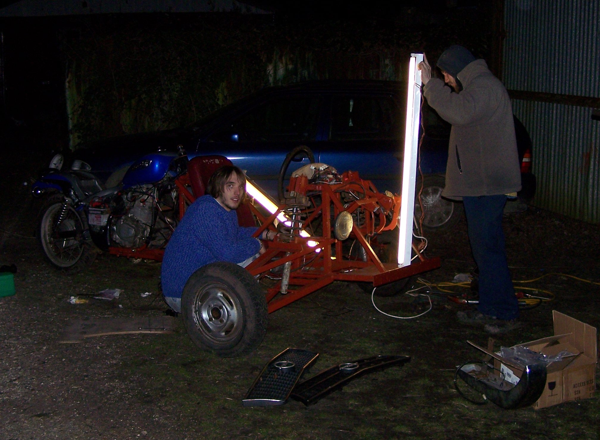
Just to show how dedicated we both are here's a photo of us (well, Larry) working through the night. The two white things are a couple of fluorescent tubes that we were using to try and see what we were doing. Shortly after this was taken we got bored of doing work and took the trike down to the field, Sitting on the back while someone else is driving and doing power slides across the grass is kinda fun (in the dark we couldn't see the skid marks we were leaving either).
Easter 2007 - Part 2
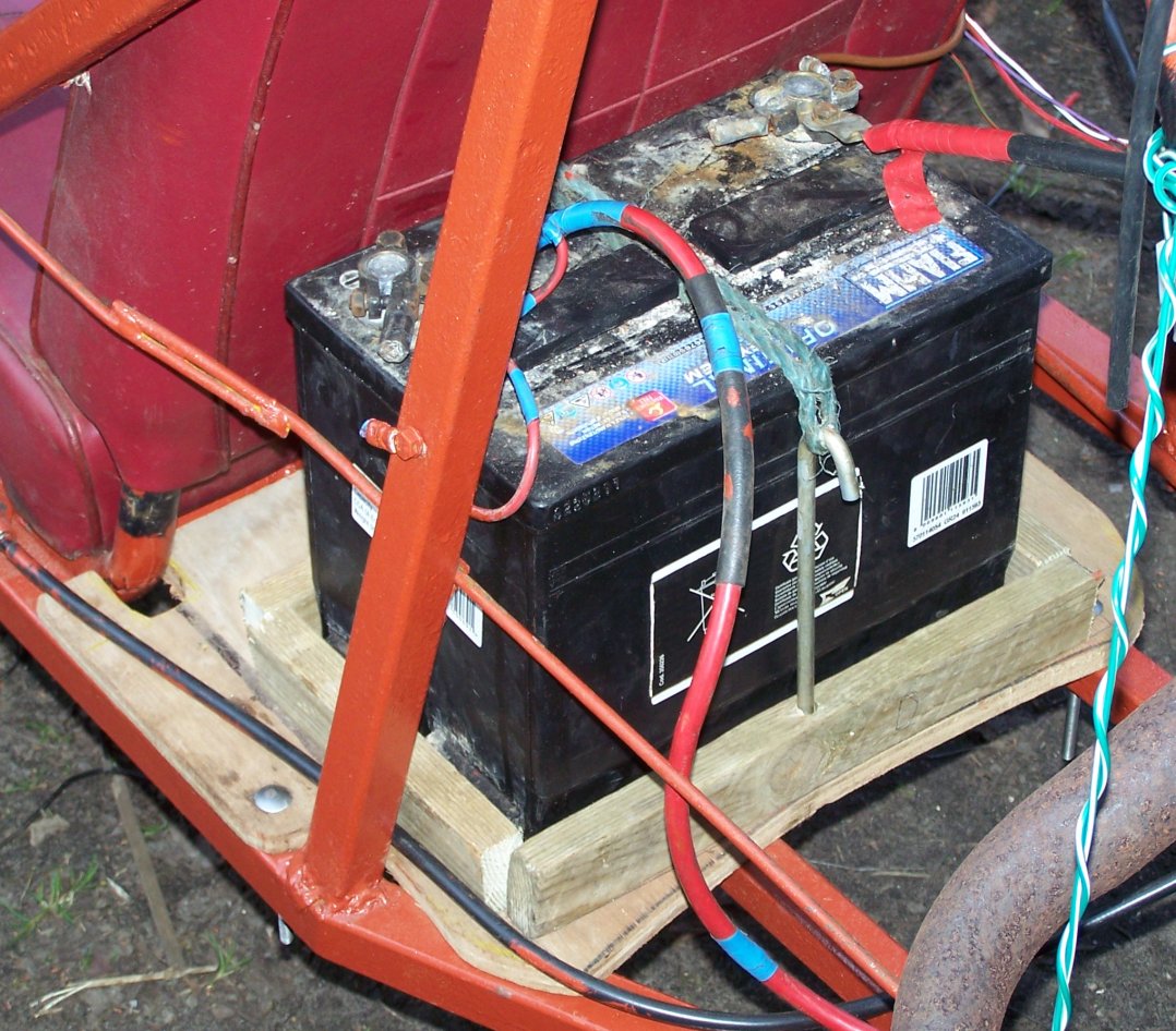
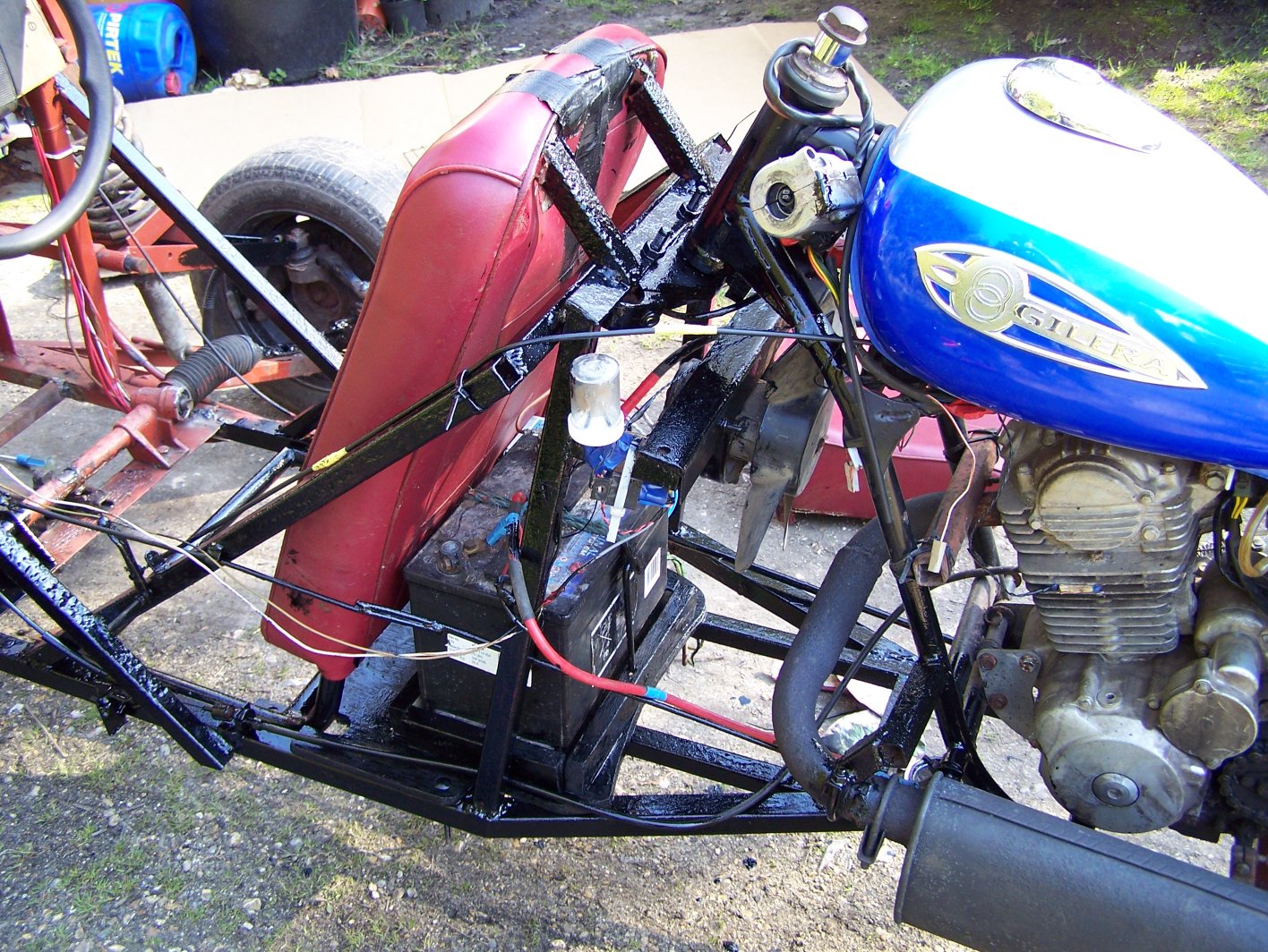
After the night-time run round the field we managed to get around to doing some more work. We've fitted some nice chrome bumpers, along with some extra metalwork to mount them to. In addition to that we made a proper holder for the extra battery - previously it was just tied on to the bare framework with rope and we managed to dislodge it going over the bumps in the field. It now sits on a piece of plywood bolted to the frame with a strap over the top. Take a look at the photos below to see the changes.
After Driving around for a while we noticed how the wooden parts that Larry had inserter into the suspension earlier in the year were starting to become crushed and pushed out of place by the loads on them. This led to us making steel replacements for them (something we'd intended to do for a long time but kept putting off). At the same time we also stiffened the suspension by making the steel replacements longer than the wooden parts. The replacements a simply pieces of large box section with a piece of plate welded to one end and slid over the shocks so that the plate rests on the spring. They have notches ground out of the other end which line up with the edges of the clamps and ensure they cannot move.
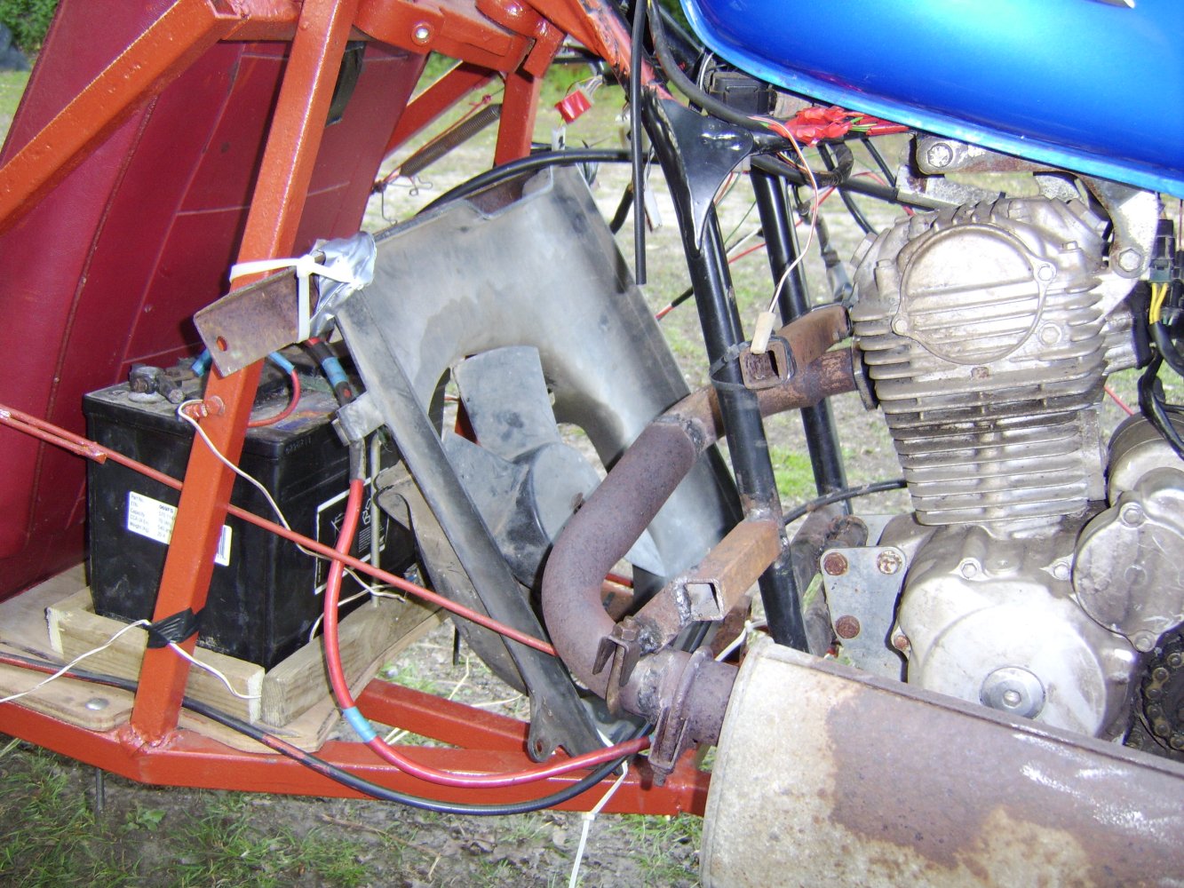
The improved suspension made driving the trike much more fun so after spending more time than usual driving it Larry noticed noticed the engine was starting to overheat. This is due to the position of the drivers seat blocking much of the airflow to the engine. To remedy this we simply added a large fan from a car radiator. This is currently controlled via a switch on the dash but eventually will be connected to a temperature sensor on the engine. The downside to this fan is that it draws around 8 amps and the bikes alternator is starting to struggle even without the lights. It does, however, make a good job of cutting the long grass in the field :-) .
Easter 2007 - Video
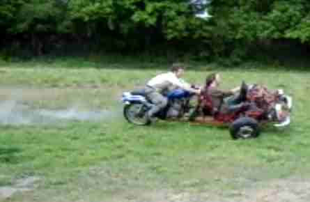
After making the changes to the trike detailed above and a few repairs to minor problems which cropped up we picked a nice sunny day and went to the farm with our friend Paul to make some videos of the trike in action. These sat on my hard-drive until August when Paul decided to have a go and spent a whole day editing them together into something presentable (Thanks Paul!). The result is available on YouTube since that means I don't have to worry about bandwidth. If anyone asks nicely though I might be able to send them a higher quality version since I know how much flash video sucks.
June 2008
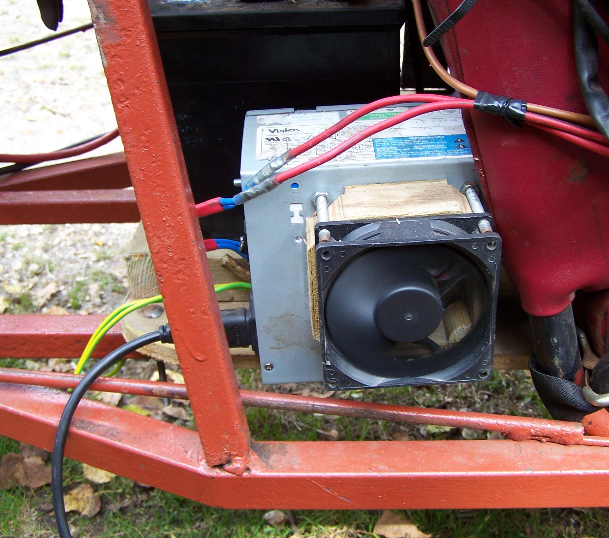
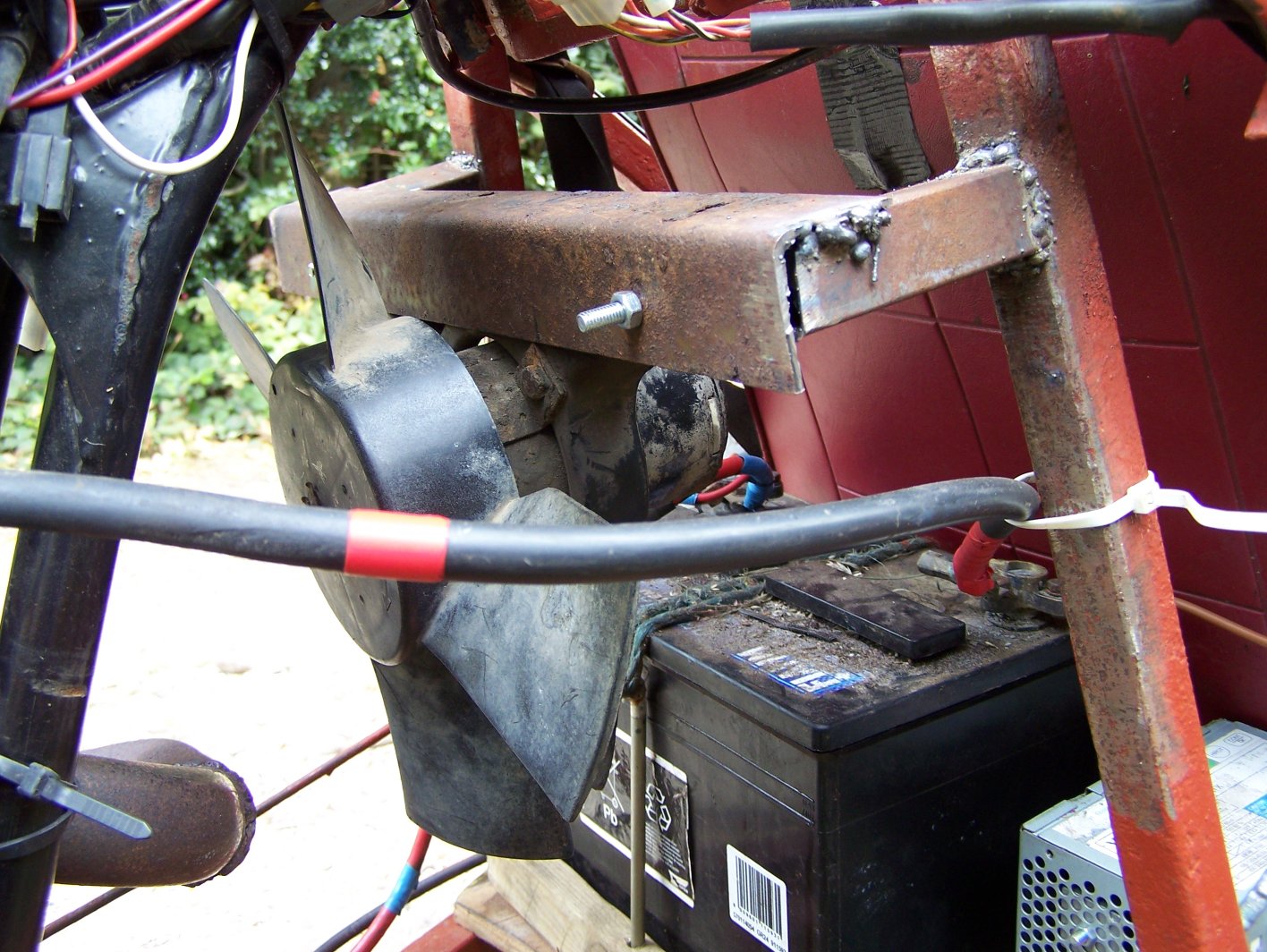
A lot has been done on the trike since the website was last updated, many, many minor fixes and a few big changes. The minor things include adding a built in battery charger to the trike, mounting the fan permanently, and connecting a cable to the choke. The pictures below show the charger and the fan mounting. The charger is built into a case from an old atx power supply but actually uses a rewound microwave oven transformer capable of delivering about 50 amps and rectified with a pair of 35 A bridge rectifiers mounted on the case to dissipate the heat. Overall output is around 14V d.c and we can have all the lights and the fan on while still putting charge into the battery. The transformer gets quite hot so there is a cooling fan mounted on the case.
The choke was connected with length of bicycle brake cable and a couple of springs, something we've been meaning to do ever since mounting the bike on the frame. It's not pretty but it works well enough. In the second picture there's a set of spring compressors on the seat ready for the first big job - the mini hubs with the knackered threads and missing drum brakes are being replaced.
Two new hubs were acquired from a rover metro to replace the mini ones. We also got the master cylinder from the metro at the same time so that we could finally have working hydraulic front brakes. We took this opportunity to shorten the arms on the suspension which made the trike a little narrower (now about 6 foot) and able to fit on a large trailer. This also made the suspension less soft and also removed the problem of the wheels leaning over on tight corners.

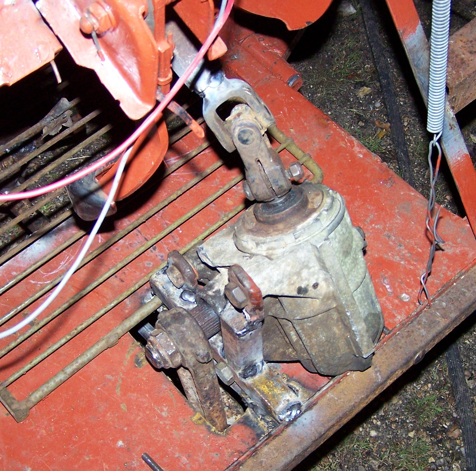
Having removed the old hubs and cut off the ends of the arms it was really just a case of welding the new ones on and reconnecting the steering rack. Shortly after this we got fed up with the cable steering repeatedly jamming and removed it totally, replacing it with a steering box from a ford transit. This was mounted right at the front of the trike with the arm pointing down through a slot in the floor. It is connected to the steering wheel by a sharf and two universal joints, all from the same transit van. The shaft passes between the clutch and brake pedals.
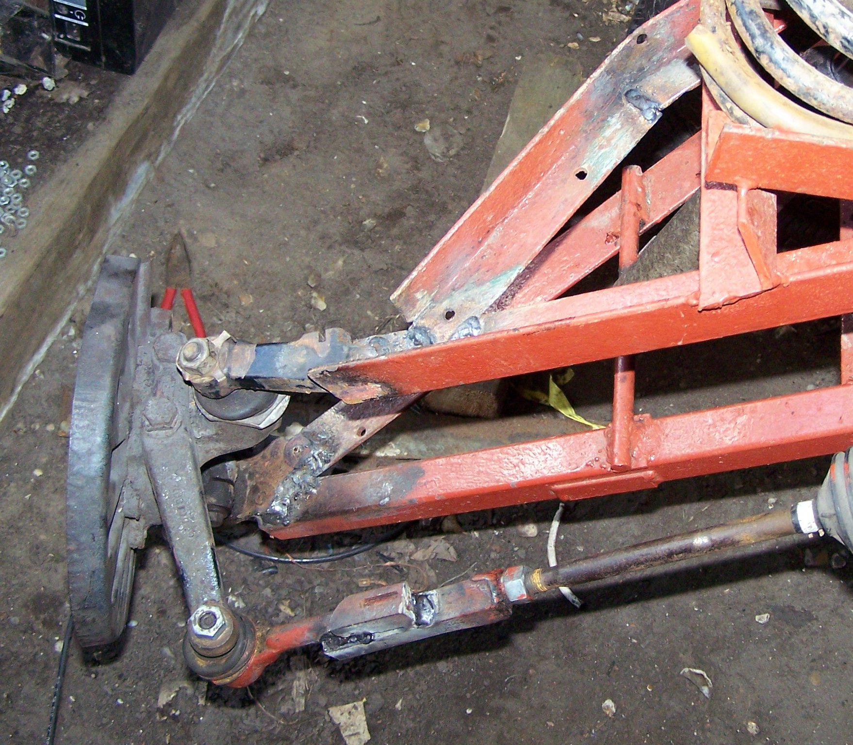
This part of the steering was all very simple to construct, although the mounting of the steering box later had to be strengthened to stop it from bending. The linkage from the steering box to the wheels however underwent several revisions before we were happy with it. The trike was turned on its side for much of this and the fuel tank therefore had to be removed.
In its final form we used a right angle crank underneath the floor of the trike to transmit the steering force to a steel pin which was welded into the middle of the original steering rack. At this point we also ended up having to weld one of the ball joints to the hub because its already damaged thread finally gave up the ghost after being taken of and put back on several times (we found it in a bucket of water so unsurprisingly the thread was more than a little rusted to start with).
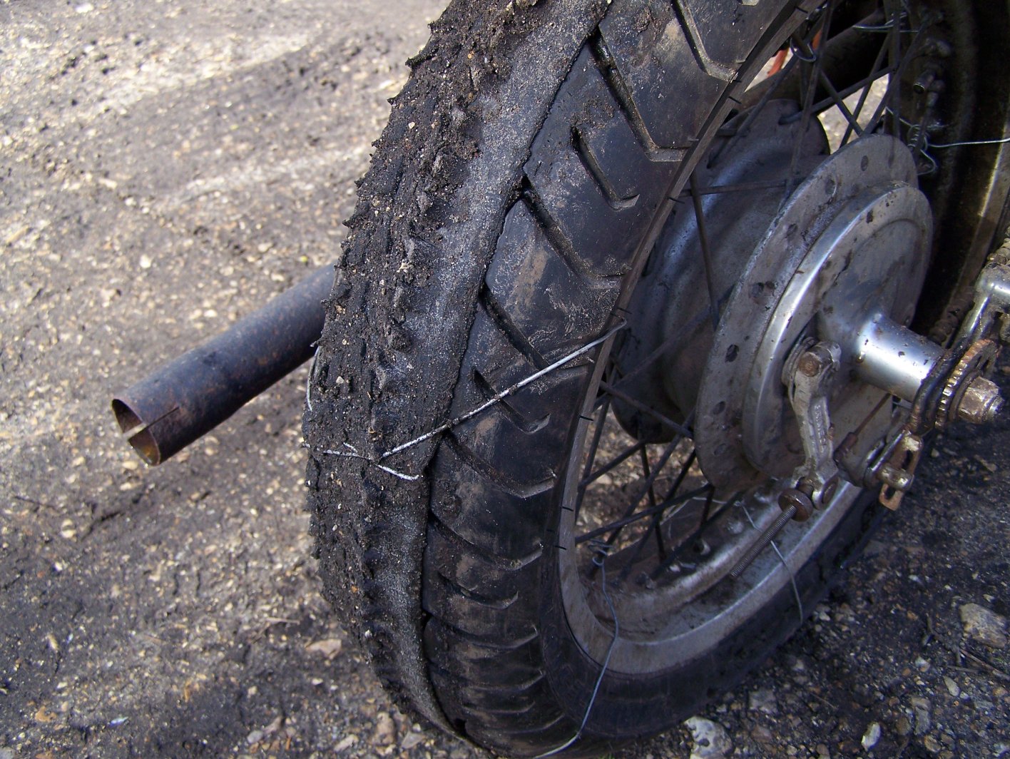
As a temporary(ish) method to improve traction on the wet grass in the field a mountain bike tyre was opend up and tied over the rear wheel of the bike with wire. This was reasonably effective and allowed us to take the trike around the field without tearing up the grass too much.
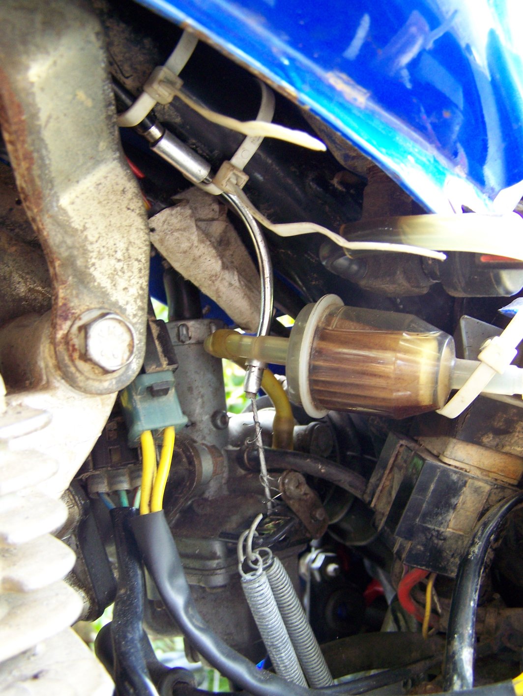
One of the last things left to do was mount a master cylinder and connect up the brakes. The master cylinder used is shown in the picture below, it is actually from a transit van as it was easier to mount than any of the others we had to hand. The vacuum servo has been removed as it is not needed and there is nothing to connect it to anyway. It is connected to the front brakes with standard copper brakeline making use of the short lengths of flexible pipe which were already attached to the brakes. Despite initially appearing to work the master cylinder later turned out to be faulty. When we find a suitable replacement we should have fully working brakes, one of the last major things we wanted to do on the trike.
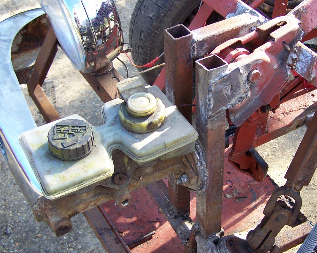
As can be seen above the frame of the trike has been painted gloss black. Also visible in the photo is a controller for the cooling fan - the electronics is mounted in the plastic container to the left of the fan and the temperature sensor is wedged in between two of the cooling fins on the engine. This controller switches on the fan using a relay when the temperature of the engine rises above a preset limit. It is currently in need of modification as it does not include any hysteresis and has a tendency to oscillate on and off as the temperature passes the switching point. This makes an annoying buzzing sound and will eventually burn out the relay contacts if it isn't fixed. As a side note a series string of LEDs was used as a voltage regulator in this circuit so it can be seen to glow green at night (chosen since green LEDs have the highest voltage drop of cheaply available types).
Update February 2009
The master cylinder has been replaced and we now have working brakes - the replacement master cylinder leaked initially but this stopped after a little while as the seals swelled up. Didn't get much chance to make new videos over the summer but we have bought a new bike to go on the back. It is a Suzuki GS 650 which will hopefully replace the Coguar this Easter.
Future plans
Most of the big jobs have now been completed. We may at some point add some bodywork and replace the temporary dash. Sometime we plan on making some more videos and possibly taking it out somewhere else for testing since the field is too short to get to any real speed. After that we'll probably spend quite a lot of time working on the new trike.
We're currently looking for somewhere else to drive the trike. It's not road-legal so up until now we've just been taking it around the field but it's getting to be rather restrictive and will be more so when we put the new bike on the back. If anyone owns or knows of somewhere we could take it within 50 miles or so of Southampton then please contact me