This undervoltage lockout circuit was designed to draw absolute minimum power in the off state, which it achieves by turning itself off. It probably wasn't really necessary to get the off current this low but it was fun. This circuit is intended for use with 18 V power tool battery packs, but can easily be adapted for other uses.
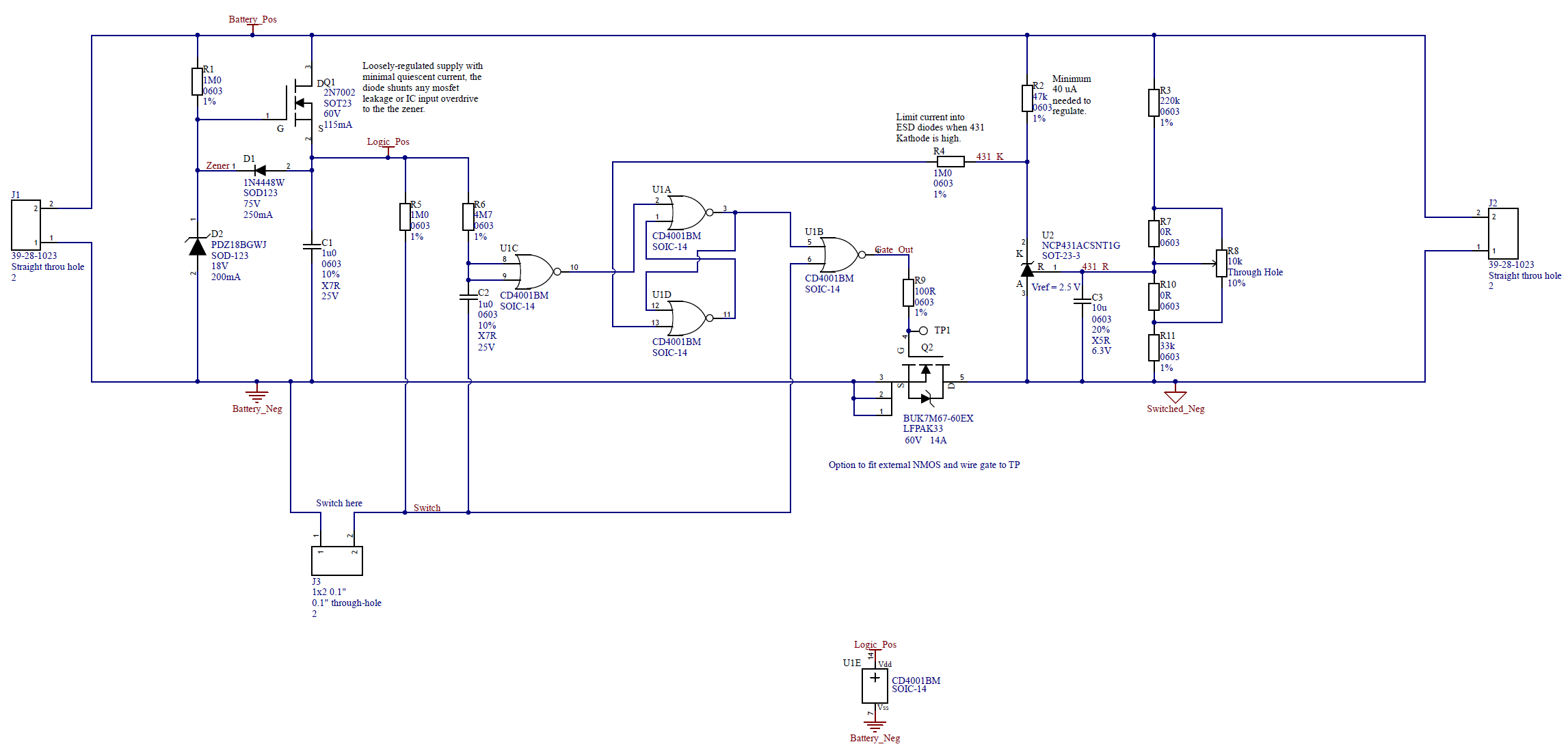
The circuit is built around a single quad CD4001 which has a quiescent current of 10 nA typical according to its datasheet. As the tool batteries can exceed it's maximum rating it is provided with a very simple supply regulator which draws around 4 μA at 20 V input. That dominates the inactive current, and falls to well under 1 μA when the battery is discharged down to the 15V cutoff threshold. The quad NOR gate is configured as a flip-flop, which is set by operating a switch, and reset by an undervoltage event. When the flip-flop is set and the switch is on, the output is turned on, which also turns on a NCP431 voltage reference/comparator (a lower current version of the TL431).
In use, the user connects the battery and turns on the switch. If the battery is OK the output comes on and stays on, if it's not it only comes on briefly for a time set by R6 and C2. Assuming it did turn on, turning off the switch will turn the output (and the voltage reference/comparator) off again via U1B. If left on then when the battery voltage eventually falls U2 will reset the flip-flop and the output will be off until the switch is turned off and then on again.
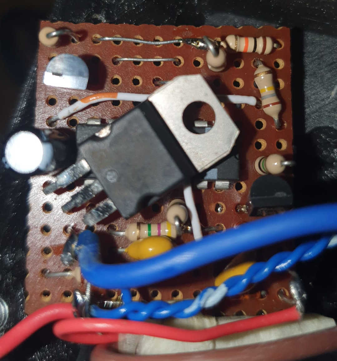
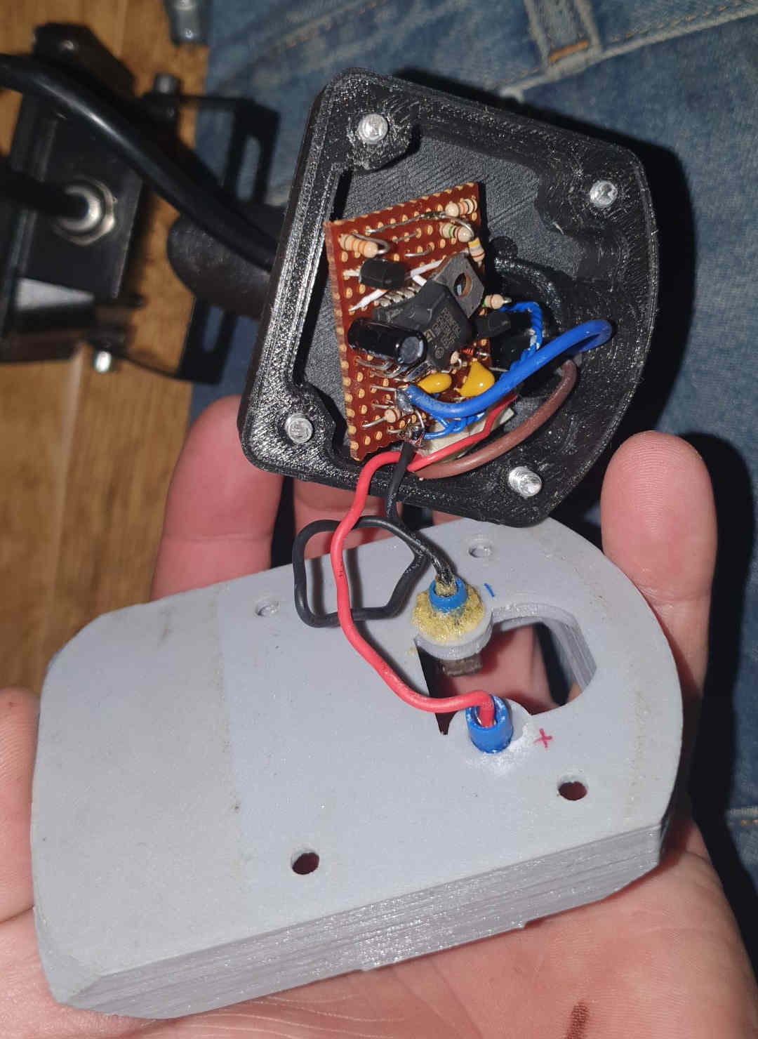
Here's the first one I made, built into a power tool battery powered LED light:
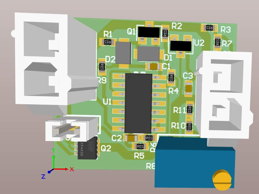
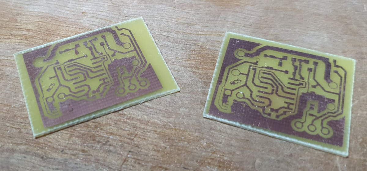
And here's a small PCB I made for it, with surface mount components. This was single sided with large clearances so it could be home-etched (the boards shown are over-etched rejects).